Cisco WS-X45-SUP6-E Hardware Maintenance Manual - Page 51
BRI Connections, provide the NT1 connection, except in North America, where the NT1 is customer owned.
 |
UPC - 882658167621
View all Cisco WS-X45-SUP6-E manuals
Add to My Manuals
Save this manual to your list of manuals |
Page 51 highlights
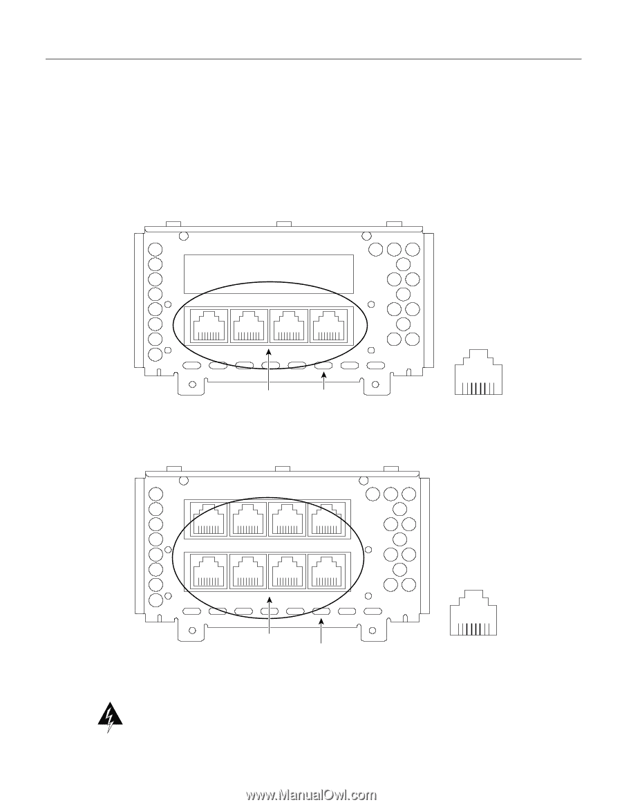
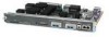
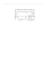
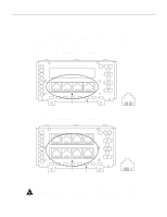
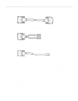
Network Connection Considerations BRI Connections The BRI network processor module (see Figure 2-31 and Figure 2-30) supports 8 Basic Rate Interface (BRI) ports. Each BRI port is an RJ-45 8-pin connector. Use an appropriate cable to connect the BRI module directly to an Integrated Services Digital Network (ISDN) through an ISDN channel service unit/digital service unit (CSU/DSU) called the NT1. The common carrier will provide the NT1 connection, except in North America, where the NT1 is customer owned. Figure 2-30 4-Port BRI Network Processor Module PORT-7 PORT-6 PORT-5 PORT-4 ISDN BRI PORT-3 PORT-2 PORT-1 PORT-0 7 6 5 4 3 2 1 0 RJ-45 BRI ports LEDs Figure 2-31 8-Port BRI Network Processor Module 87654321 H2520 PORT-7 PORT-6 PORT-5 ISDN BRI PORT-4 H2412 PORT-3 PORT-2 PORT-1 PORT-0 7 6 5 4 3 2 1 0 RJ-45 BRI ports LEDs 87654321 Warning Network hazardous voltages are accessible in the BRI cable. If you detach the BRI cable, detach the end away from the router first to avoid possible electric shock. Network hazardous voltages are also accessible on the BRI module in the area of the BRI port (RJ-45 connector), even when power is turned OFF. (See Figure 2-30 and Figure 2-31.) Preparing for Installation 2-29
-
 1
1 -
2
-
3
-
4
-
5
-
6
-
7
-
8
-
9
-
10
-
11
-
12
-
13
-
14
-
15
-
16
-
17
-
18
-
19
-
20
-
21
-
22
-
23
-
24
-
25
-
26
-
27
-
28
-
29
-
30
-
31
-
32
-
33
-
34
-
35
-
36
-
37
-
38
-
39
-
40
-
41
-
42
-
43
-
44
-
45
-
 46
46 -
 47
47 -
 48
48 -
 49
49 -
 50
50 -
 51
51 -
 52
52 -
 53
53 -
 54
54 -
 55
55 -
 56
56 -
57
-
58
-
59
-
60
-
61
-
62
-
63
-
64
-
65
-
66
-
67
-
68
-
69
-
70
-
71
-
72
-
73
-
74
-
75
-
76
-
77
-
78
-
79
-
80
-
81
-
82
-
83
-
84
-
85
-
86
-
87
-
88
-
89
-
90
-
91
-
92
-
93
-
94
-
95
-
96
-
97
-
98
-
99
-
100
-
101
-
102
-
103
-
104
-
105
-
106
-
107
-
108
-
109
-
110
-
111
-
112
-
113
-
114
-
115
-
116
-
117
-
118
-
119
-
120
-
121
-
122
-
123
-
124
-
125
-
126
-
127
-
128
-
129
-
130
-
131
-
132
-
133
-
134
-
135
-
136
-
137
-
138
-
139
-
140
-
141
-
142
-
143
 |
 |