Cisco WS-X45-SUP6-E Hardware Maintenance Manual - Page 44
Inverting the Clock Signal on the Four-Port Serial Module
 |
UPC - 882658167621
View all Cisco WS-X45-SUP6-E manuals
Add to My Manuals
Save this manual to your list of manuals |
Page 44 highlights
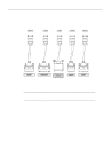
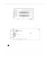
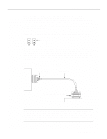
Network Connection Considerations Configuring the Four-Port Serial Module Interfaces The following sections describe the commands for configuring an external clock signal for a DCE interface and for configuring a port for NRZI encoding or 32-bit CRC. Configuration commands are executed from the privileged level of the EXEC command interpreter. Configuring the Four-Port Serial Module Timing (Clock) Signals All interfaces support both DTE and DCE mode, depending on the mode of the interface cable attached to the port. To use a port as a DTE interface, connect a DTE adapter cable to the port. When the system detects the DTE mode cable, it automatically uses the external timing signal. To use a port in DCE mode, you must connect a DCE interface cable and set the clock speed with the clockrate configuration command. This section describes how to set the clock rate on a DCE port and, if necessary, how to invert the clock to correct a phase shift between the data and clock signals. Setting the Four-Port Serial Module Clock Rate All DCE interfaces require a noninverted internal transmit clock signal, which is generated by the serial module. The default operation on a DCE interface is for the DCE device to generate its own clock signal (TXC) and send it to the remote DTE. The remote DTE device returns the clock signal to the DCE. The clockrate command specifies the rate as a bits-per-second value. In the following example, the clock rate for the top serial interface on a dual serial module is defined as 72 Kbps: interface serial 1 clockrate 72000 Use the no clockrate command to remove the clock rate for DTE operation. Following are the acceptable clockrate settings: 1200 2400 4800 9600 19200 38400 56000 64000 72000 125000 148000 500000 800000 1000000 1300000 2000000 4000000 Speeds above 64 Kbps (64000) are not supported for EIA/TIA-232. On all interface types, if your cable lengths exceed the standard recommendations, faster speeds might not work. Inverting the Clock Signal on the Four-Port Serial Module Systems that use long cables may experience high error rates when operating at the higher transmission speeds. Slight variances in cable construction, temperature, and other factors can cause the clock and data signals to shift out of phase. If a DCE port is reporting a high number of error packets, suspect a phase shift. Inverting the clock can often correct this shift. When a port is operating in DCE mode, the default operation is for the attached DTE device to return the clock signal (SCTE) to the DCE port. The DCE sends SCT and SCR clock signals to the DTE, and DTE returns an SCTE clock signal to the DCE. If the DTE device does not return SCTE, you must use the dce-terminal-timing-enable command to configure the DCE port to use its own clock signal in place of the SCTE signal that would normally be returned from the DTE device. To configure an interface to accept the internal clock generated by the serial module in place of the SCTE clock that is normally returned by the DTE device, specify the interface followed by the dce-terminal-timing-enable command. In the example that follows, the serial 0 port is configured to accept the internal clock signal: interface serial 0 dce-terminal-timing-enable 2-22 Cisco 4000 Series Hardware Installation and Maintenance
-
 1
1 -
2
-
3
-
4
-
5
-
6
-
7
-
8
-
9
-
10
-
11
-
12
-
13
-
14
-
15
-
16
-
17
-
18
-
19
-
20
-
21
-
22
-
23
-
24
-
25
-
26
-
27
-
28
-
29
-
30
-
31
-
32
-
33
-
34
-
35
-
36
-
37
-
38
-
 39
39 -
 40
40 -
 41
41 -
 42
42 -
 43
43 -
 44
44 -
 45
45 -
 46
46 -
 47
47 -
 48
48 -
 49
49 -
50
-
51
-
52
-
53
-
54
-
55
-
56
-
57
-
58
-
59
-
60
-
61
-
62
-
63
-
64
-
65
-
66
-
67
-
68
-
69
-
70
-
71
-
72
-
73
-
74
-
75
-
76
-
77
-
78
-
79
-
80
-
81
-
82
-
83
-
84
-
85
-
86
-
87
-
88
-
89
-
90
-
91
-
92
-
93
-
94
-
95
-
96
-
97
-
98
-
99
-
100
-
101
-
102
-
103
-
104
-
105
-
106
-
107
-
108
-
109
-
110
-
111
-
112
-
113
-
114
-
115
-
116
-
117
-
118
-
119
-
120
-
121
-
122
-
123
-
124
-
125
-
126
-
127
-
128
-
129
-
130
-
131
-
132
-
133
-
134
-
135
-
136
-
137
-
138
-
139
-
140
-
141
-
142
-
143
 |
 |