Coby TFDVD3297 Instruction Manual - Page 10
Unit's rear panel
 |
UPC - 716829943274
View all Coby TFDVD3297 manuals
Add to My Manuals
Save this manual to your list of manuals |
Page 10 highlights
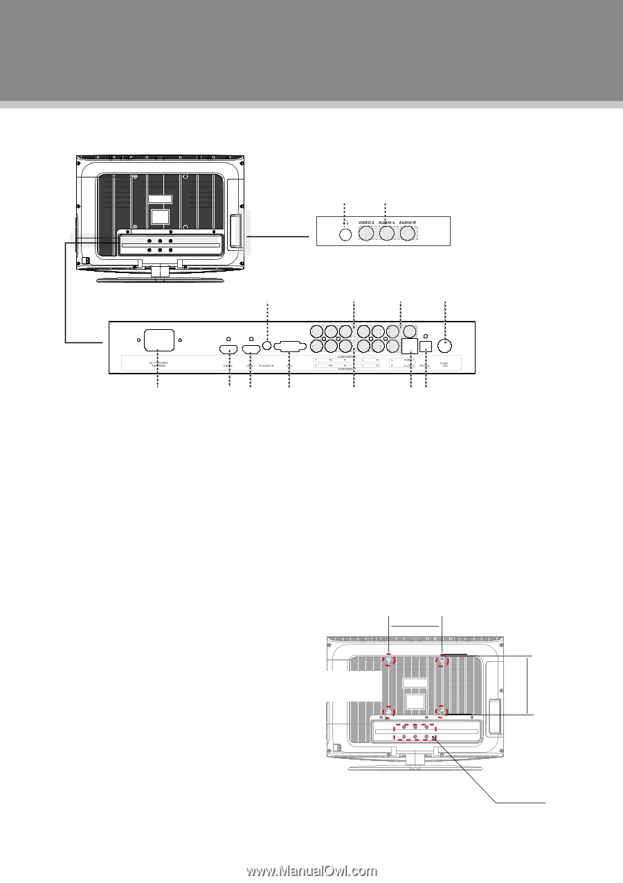
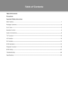
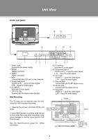
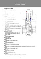
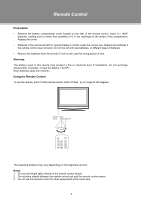
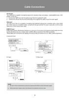
Unit's rear panel Unit View 12 13 > 8 9 10 11 > 1 23 4 1. Power Jack Connect to the power supply. 2. HDMI2 HDMI2 connector 3. HDMI1 HDMI1 connector. 4. VGA Connect with the VGA port on the computer. 5. Component Input1 YCb/Pb Cr/Pr - - Input the video signal. L, R - - Input the audio signal. 6. S-VIDEO1 Input the S-Video signal. 7. OPTICAL Out Connect with the digital audio decoder. Wall Mounting The TV case can be attached onto the wall, using the VESA standard mounting. 5 67 8. PC Audio In Input the PC audio signal. 9. Component Input 2 YCb/Pb Cr/Pr - - Input the video signal. L, R - - Input the audio signal. 10. AV1 Input VIDEO 1 - - Input the video signal. L, R - - Input the audio signal. 11. Antenna Jack Connect with the TV RF signal source. 12. Phone Jack Connect with the stereo phone. 13. AV2 Input VIDEO 2 - - Input the video signal. L, R - - Input the audio signal. 200mm < > > 1. Release the screws and take off the unit stand. MACHINE THREAD x4 VESA STANDARD M5 2. Use VESA standard mountings to fix the unit onto the wall. Take care when mounting, it may cause damage or serious injury should it fall from the wall. See the Specifications page for VESA information. e.g. TFDVD 2697 REAR CABINET < 200mm RELEASE SCREWS AND TAKE OFF THE STAND 4
-
 1
1 -
2
-
3
-
4
-
 5
5 -
 6
6 -
 7
7 -
 8
8 -
 9
9 -
 10
10 -
 11
11 -
 12
12 -
 13
13 -
 14
14 -
 15
15 -
16
-
17
-
18
-
19
-
20
-
21
-
22
-
23
-
24
-
25
-
26
-
27
-
28
-
29
 |
 |