Compaq 6000 Maintenance & Service Guide: HP Compaq 6000 Pro Microtower Bus - Page 170
Front Fan Assembly
 |
UPC - 894582579463
View all Compaq 6000 manuals
Add to My Manuals
Save this manual to your list of manuals |
Page 170 highlights
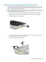
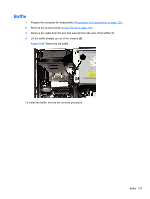
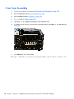
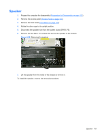
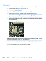
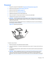
Front Fan Assembly 1. Prepare the computer for disassembly (Preparation for Disassembly on page 122). 2. Remove the access panel (Access Panel on page 123). 3. Remove the front bezel (Front Bezel on page 124). 4. Remove the baffle (Baffle on page 157). 5. Disconnect the fan cable from the system board (CH FAN1, P9). 6. On the front of the computer, press the left and bottom tabs to disengage the fan assembly from the chassis. Figure 9-46 Removing the chassis fan 7. Lift the assembly out of the chassis. To install the chassis fan, reverse the removal procedure. Be sure to orient the air flow into the unit. 158 Chapter 9 Removal and Replacement Procedures Small Form Factor (SFF) Chassis
-
 1
1 -
2
-
3
-
4
-
5
-
6
-
7
-
8
-
9
-
10
-
11
-
12
-
13
-
14
-
15
-
16
-
17
-
18
-
19
-
20
-
21
-
22
-
23
-
24
-
25
-
26
-
27
-
28
-
29
-
30
-
31
-
32
-
33
-
34
-
35
-
36
-
37
-
38
-
39
-
40
-
41
-
42
-
43
-
44
-
45
-
46
-
47
-
48
-
49
-
50
-
51
-
52
-
53
-
54
-
55
-
56
-
57
-
58
-
59
-
60
-
61
-
62
-
63
-
64
-
65
-
66
-
67
-
68
-
69
-
70
-
71
-
72
-
73
-
74
-
75
-
76
-
77
-
78
-
79
-
80
-
81
-
82
-
83
-
84
-
85
-
86
-
87
-
88
-
89
-
90
-
91
-
92
-
93
-
94
-
95
-
96
-
97
-
98
-
99
-
100
-
101
-
102
-
103
-
104
-
105
-
106
-
107
-
108
-
109
-
110
-
111
-
112
-
113
-
114
-
115
-
116
-
117
-
118
-
119
-
120
-
121
-
122
-
123
-
124
-
125
-
126
-
127
-
128
-
129
-
130
-
131
-
132
-
133
-
134
-
135
-
136
-
137
-
138
-
139
-
140
-
141
-
142
-
143
-
144
-
145
-
146
-
147
-
148
-
149
-
150
-
151
-
152
-
153
-
154
-
155
-
156
-
157
-
158
-
159
-
160
-
161
-
162
-
163
-
164
-
 165
165 -
 166
166 -
 167
167 -
 168
168 -
 169
169 -
 170
170 -
 171
171 -
 172
172 -
 173
173 -
 174
174 -
 175
175 -
176
-
177
-
178
-
179
-
180
-
181
-
182
-
183
-
184
-
185
-
186
-
187
-
188
-
189
-
190
-
191
-
192
-
193
-
194
-
195
-
196
-
197
-
198
-
199
-
200
-
201
-
202
-
203
-
204
-
205
-
206
-
207
-
208
-
209
-
210
-
211
-
212
-
213
-
214
-
215
-
216
-
217
-
218
-
219
-
220
-
221
-
222
-
223
-
224
-
225
-
226
-
227
-
228
-
229
-
230
-
231
-
232
-
233
-
234
-
235
-
236
-
237
-
238
-
239
-
240
-
241
-
242
-
243
-
244
-
245
-
246
-
247
-
248
-
249
-
250
-
251
-
252
-
253
-
254
-
255
-
256
-
257
 |
 |

Front Fan Assembly
1.
Prepare the computer for disassembly (
Preparation for Disassembly
on page
122
).
2.
Remove the access panel (
Access Panel
on page
123
).
3.
Remove the front bezel (
Front Bezel
on page
124
).
4.
Remove the baffle (
Baffle
on page
157
).
5.
Disconnect the fan cable from the system board (CH FAN1, P9).
6.
On the front of the computer, press the left and bottom tabs to disengage the fan assembly from
the chassis.
Figure 9-46
Removing the chassis fan
7.
Lift the assembly out of the chassis.
To install the chassis fan, reverse the removal procedure. Be sure to orient the air flow into the unit.
158
Chapter 9
Removal and Replacement Procedures Small Form Factor (SFF) Chassis