Compaq Evo n600c Compaq Evo Notebook N600c, N610c, N610v and N620c Notebook PC - Page 137
Switch Cover
 |
View all Compaq Evo n600c manuals
Add to My Manuals
Save this manual to your list of manuals |
Page 137 highlights
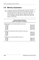
Removal and Replacement Procedures 5.10 Switch Cover Switch Cover Spare Part Number Information Switch cover 241438-001 1. Prepare the notebook for disassembly (Section 5.3). 2. Remove the keyboard (Section 5.7). 3. Position the notebook so the rear panel faces you. 4. Remove the two black TM2.5 × 7.0 screws that secure the switch cover to the base enclosure (Figure 5-16). Figure 5-16. Removing the Switch Cover Screws Maintenance and Service Guide 5-27
-
 1
1 -
2
-
3
-
4
-
5
-
6
-
7
-
8
-
9
-
10
-
11
-
12
-
13
-
14
-
15
-
16
-
17
-
18
-
19
-
20
-
21
-
22
-
23
-
24
-
25
-
26
-
27
-
28
-
29
-
30
-
31
-
32
-
33
-
34
-
35
-
36
-
37
-
38
-
39
-
40
-
41
-
42
-
43
-
44
-
45
-
46
-
47
-
48
-
49
-
50
-
51
-
52
-
53
-
54
-
55
-
56
-
57
-
58
-
59
-
60
-
61
-
62
-
63
-
64
-
65
-
66
-
67
-
68
-
69
-
70
-
71
-
72
-
73
-
74
-
75
-
76
-
77
-
78
-
79
-
80
-
81
-
82
-
83
-
84
-
85
-
86
-
87
-
88
-
89
-
90
-
91
-
92
-
93
-
94
-
95
-
96
-
97
-
98
-
99
-
100
-
101
-
102
-
103
-
104
-
105
-
106
-
107
-
108
-
109
-
110
-
111
-
112
-
113
-
114
-
115
-
116
-
117
-
118
-
119
-
120
-
121
-
122
-
123
-
124
-
125
-
126
-
127
-
128
-
129
-
130
-
131
-
 132
132 -
 133
133 -
 134
134 -
 135
135 -
 136
136 -
 137
137 -
 138
138 -
 139
139 -
 140
140 -
 141
141 -
 142
142 -
143
-
144
-
145
-
146
-
147
-
148
-
149
-
150
-
151
-
152
-
153
-
154
-
155
-
156
-
157
-
158
-
159
-
160
-
161
-
162
-
163
-
164
-
165
-
166
-
167
-
168
-
169
-
170
-
171
-
172
-
173
-
174
-
175
-
176
-
177
-
178
-
179
-
180
-
181
-
182
-
183
-
184
-
185
-
186
-
187
-
188
-
189
-
190
-
191
-
192
-
193
-
194
-
195
-
196
-
197
-
198
-
199
-
200
-
201
-
202
-
203
-
204
-
205
-
206
-
207
-
208
-
209
-
210
-
211
-
212
-
213
-
214
-
215
-
216
-
217
 |
 |

Removal and Replacement Procedures
Maintenance and Service Guide
5–27
5.10 Switch Cover
1. Prepare the notebook for disassembly (Section 5.3).
2. Remove the keyboard (Section 5.7).
3. Position the notebook so the rear panel faces you.
4. Remove the two black TM2.5 × 7.0 screws that secure the
switch cover to the base enclosure (Figure 5-16).
Figure 5-16. Removing the Switch Cover Screws
Switch Cover
Spare Part Number Information
Switch cover
241438-001