Compaq d530 HP Compaq Business Desktop d500 Service Reference Guide, 5th Editi - Page 123
Expansion Card Cage, the Smart Cover Sensor.
 |
View all Compaq d530 manuals
Add to My Manuals
Save this manual to your list of manuals |
Page 123 highlights
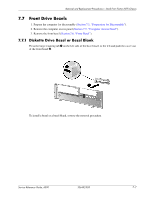
Removal and Replacement Procedures- Small Form Factor (SFF) Chassis 6. Repeat steps 4 and 5 for any additional modules that you want to install. ✎ The computer automatically recognizes the additional memory when the computer is turned on. To reassemble the computer, reverse the removal procedure. ✎ If you normally lock the Smart Cover Lock, use Computer Setup to relock the lock and enable the Smart Cover Sensor. 7.9 Expansion Card Cage 1. If you have locked the Smart Cover Lock, use Computer Setup to unlock the lock (Section 7.2, "Unlocking the Smart Cover Lock"). 2. Prepare the computer for disassembly (Section 7.1, "Preparation for Disassembly"). 3. Remove the computer access panel (Section 7.5, "Computer Access Panel"). 4. .Disconnect all cables attached to the expansion cards. 5. Grasp the expansion card cage by the green labels (the cage in the computer has two spots marked 1) and pull it straight up from the chassis. To install the card cage, reverse the removal procedures. Service Reference Guide, d500 336492-005 7-9
-
 1
1 -
2
-
3
-
4
-
5
-
6
-
7
-
8
-
9
-
10
-
11
-
12
-
13
-
14
-
15
-
16
-
17
-
18
-
19
-
20
-
21
-
22
-
23
-
24
-
25
-
26
-
27
-
28
-
29
-
30
-
31
-
32
-
33
-
34
-
35
-
36
-
37
-
38
-
39
-
40
-
41
-
42
-
43
-
44
-
45
-
46
-
47
-
48
-
49
-
50
-
51
-
52
-
53
-
54
-
55
-
56
-
57
-
58
-
59
-
60
-
61
-
62
-
63
-
64
-
65
-
66
-
67
-
68
-
69
-
70
-
71
-
72
-
73
-
74
-
75
-
76
-
77
-
78
-
79
-
80
-
81
-
82
-
83
-
84
-
85
-
86
-
87
-
88
-
89
-
90
-
91
-
92
-
93
-
94
-
95
-
96
-
97
-
98
-
99
-
100
-
101
-
102
-
103
-
104
-
105
-
106
-
107
-
108
-
109
-
110
-
111
-
112
-
113
-
114
-
115
-
116
-
117
-
 118
118 -
 119
119 -
 120
120 -
 121
121 -
 122
122 -
 123
123 -
 124
124 -
 125
125 -
 126
126 -
 127
127 -
 128
128 -
129
-
130
-
131
-
132
-
133
-
134
-
135
-
136
-
137
-
138
-
139
-
140
-
141
-
142
-
143
-
144
-
145
-
146
-
147
-
148
-
149
-
150
-
151
-
152
-
153
-
154
-
155
-
156
-
157
-
158
-
159
-
160
-
161
-
162
-
163
-
164
-
165
-
166
-
167
-
168
-
169
-
170
-
171
-
172
-
173
-
174
-
175
-
176
-
177
-
178
-
179
-
180
-
181
-
182
-
183
-
184
-
185
-
186
-
187
-
188
-
189
-
190
-
191
-
192
-
193
-
194
-
195
-
196
-
197
-
198
-
199
-
200
-
201
-
202
-
203
-
204
-
205
-
206
-
207
-
208
-
209
-
210
-
211
-
212
-
213
-
214
-
215
-
216
-
217
-
218
-
219
-
220
-
221
-
222
-
223
-
224
-
225
-
226
-
227
-
228
-
229
-
230
-
231
-
232
-
233
-
234
 |
 |
