Craftsman 17540 Operation Manual - Page 15
Installing And Removing The Cutting Bit Figs. 3, 4 And 4a - router 1 2 inch collet
 |
View all Craftsman 17540 manuals
Add to My Manuals
Save this manual to your list of manuals |
Page 15 highlights
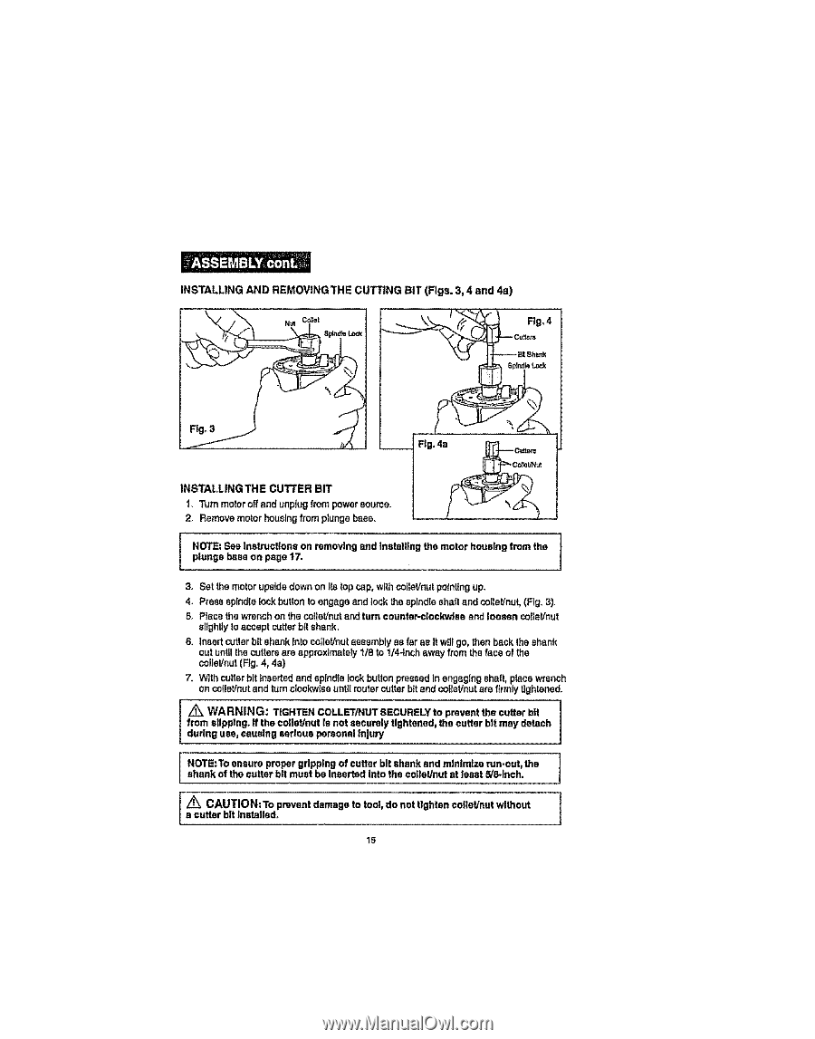
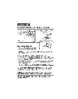
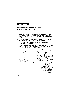
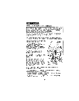
INSTALLING AND REMOVING THE CUTTING BIT (Figs. 3, 4 and 4a) _ Fig° 4 --Bit Shank INSTALLING THE CUTTER BIT 1, Turn motoroff and unplugfrom power source. 2. Remove motor housingfrom plunge base. NOTE: See Instructions on removing and Installing the motor housing from the plunge base on page 17. 3. Set the molar upsidedown on Its top cap, with cofleVnutpotnUngup. 4. Press spindlelock buttonto engage and lock the splndte shaft and caller!nut,(Fig. 3), 5. Place the wrench on the coIlal/nutand turn countar-clockw|se and loosen colleVnut eNghtlyto accept cutterbit shank, 6. Insert cutter bit shank lnlo coflel/nutassembly as far ae It will go, then back the shank out untllthecuttersare approximately 1t8 to 1/4-Inchaway fromthe face of the coileVnut(Fig° 4, 4a) 7. With culler bit Inserted and spindlelock bulton pressed In engaging shaft, place wrench on collet/nutand turn clockwiseunU[router cutter bit and cotlaVnutera firmly lightened. WARNING: TIGHTEN COLLETiNUT SECURELY to prevent the cutter bit from slipping, ff the caller/nut Is not securely tightened, the cutter bit may detach during use, causing serious personal injury NOTE:To ensure proper gripping of cutter bit shank and minimize run-out_ the shank of the cutter bit must be Inserted Into the caller/nut at least 5/8-inch, /_ CAUTION'To prevent damage to tool, do not tighten coltet/nut without a cutter bit Installed° 15
-
 1
1 -
2
-
3
-
4
-
5
-
6
-
7
-
8
-
9
-
 10
10 -
 11
11 -
 12
12 -
 13
13 -
 14
14 -
 15
15 -
 16
16 -
 17
17 -
 18
18 -
 19
19 -
 20
20 -
21
-
22
-
23
-
24
-
25
-
26
-
27
-
28
-
29
-
30
-
31
-
32
-
33
-
34
-
35
-
36
-
37
-
38
-
39
-
40
 |
 |