Craftsman 17540 Operation Manual - Page 17
INSTALLING ROUTER MOTOR, tN BASE Rg, 5, unplug, powersource, Slide, motorIntothebase, tlwittgoE
 |
View all Craftsman 17540 manuals
Add to My Manuals
Save this manual to your list of manuals |
Page 17 highlights
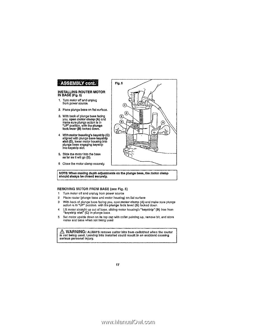
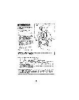
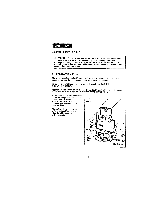
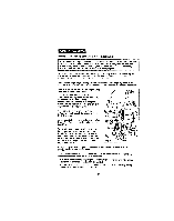
Fig. 5 INSTALLING ROUTER MOTOR tN BASE (Rg, 5) 1, Turnmotoroffandunplug from powersource, 2. Place plunge bass on fiat surface. 3_ With back ofplunge base facing you,open motor clamp (A) and make sure plunge action Is In "UP" poslt[on,with theplunge lock laver (B) locked down. 4. Wtthmotor houslng'a kayatrlp (C) aligned with ptungabass ksystrlp slot (D), lower motor housingInto Fnlungebase engaging keyetdp _okeyetdp-sloL 5, Slidethe motorIntothebase as faras tl wittgo(E), B, Close the motor clamp securely. I NshOoTuEld: Walhweanyms abledncglodsedpthseacdujrueslytm. ents on the plunge base, the motor clamp REMOVING MOTOR FROM BASE (see Fig_ 5) 1 Turn motor off and unplug from power source 2 Place router (plunge base and meier housing) on ll_t surface 3 With back of plunge base factng you, open motor clamp (A) and make sure plunge action is in "UP" position, with the plunge lock lever (B) locked down 4 Lift motor straight up oul of base, eliding motor houstng'e"keystrtp" (B) tree from "keyetrlp slot" (C) in plunge base 5 Set motor upside down on its top sap with so,let pointing up, remove bit, and slore motor and base when not being used Z_ WARNING: ALWAYS remove culler bits lrom colleb'nut when the router ] Is not bethg used. Leaving bits installed could result in an accident causing sertous personal lnjury_ I 17
-
 1
1 -
2
-
3
-
4
-
5
-
6
-
7
-
8
-
9
-
10
-
11
-
 12
12 -
 13
13 -
 14
14 -
 15
15 -
 16
16 -
 17
17 -
 18
18 -
 19
19 -
 20
20 -
 21
21 -
 22
22 -
23
-
24
-
25
-
26
-
27
-
28
-
29
-
30
-
31
-
32
-
33
-
34
-
35
-
36
-
37
-
38
-
39
-
40
 |
 |