Craftsman 21194 Operation Manual - Page 23
° Bevel Pointer
 |
View all Craftsman 21194 manuals
Add to My Manuals
Save this manual to your list of manuals |
Page 23 highlights
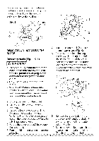
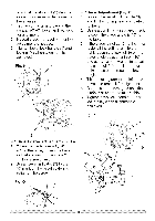
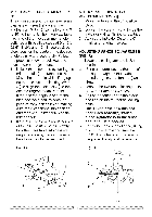
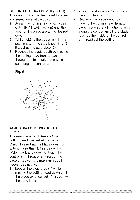
to adjust the stop bolt (3) depth in or out to increase or decrease the bevel angle. 4. Tilt the cutting arm to back to the right at 90 ° (0°) bevel and recheck for alignment. 5. Repeat steps 1 through 4 if further adjustment is needed. 6. Tighten bevel lock handle (1) and Iocknut (4) when alignment is achieved. Fig. N 3 \ 4 45 ° Bevel Adjustment (Fig. P) 1. Loosen the bevel lock handle (8) and tilt the cutting head completely to the left. 2. Using a combination square, check to see if the blade angle is 45 ° to the table. 3. If the blade is not at 45 ° to the miter table, tilt the cutting arm to the right, loosen the Iocknut (9) on the bevel angle adjustment bolt (10) and use a 10 mm wrench to adjust the stop bolt (10) depth in or out to increase or decrease the bevel angle. 4. Tilt the cutting arm to the left to 45 ° bevel and recheck for alignment. 5. Repeat steps 1 through 4 until the blade is at 45 ° to the miter table. 6. Tighten bevel lock handle (8) and Iocknut (9) when alignment is achieved. Fig. P 2 5 90 ° Bevel Pointer Adjustment (Fig. O) 1. When the blade is exactly 90 ° (0°) to the table, loosen the bevel indicator screw (6) using a # 2 Phillips screwdriver. 2. Adjust bevel indicator (7) to the "0" mark on the bevel scale and retighten the screw. Fig. 0 \7
-
 1
1 -
2
-
3
-
4
-
5
-
6
-
7
-
8
-
9
-
10
-
11
-
12
-
13
-
14
-
15
-
16
-
17
-
 18
18 -
 19
19 -
 20
20 -
 21
21 -
 22
22 -
 23
23 -
 24
24 -
 25
25 -
 26
26 -
 27
27 -
 28
28 -
29
-
30
-
31
-
32
-
33
-
34
-
35
-
36
-
37
-
38
-
39
-
40
-
41
-
42
-
43
-
44
 |
 |
