Craftsman 21194 Operation Manual - Page 31
CUT FIG. X
 |
View all Craftsman 21194 manuals
Add to My Manuals
Save this manual to your list of manuals |
Page 31 highlights
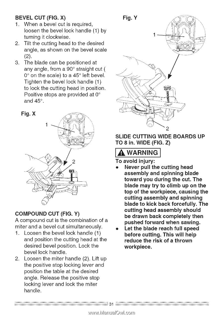
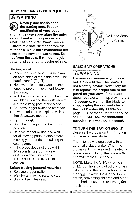
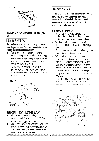
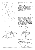
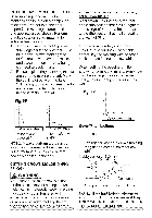
BEVEL CUT (FIG. X) Fig. Y 1. When a bevel cut is required, \ loosen the bevel lock handle (1) by turning it clockwise. 2. Tilt the cutting head to the desired angle, as shown on the bevel scale (2). 3. The blade can be positioned at any angle, from a 90 ° straight cut ( 0 ° on the scale) to a 45 ° left bevel. Tighten the bevel lock handle (1) to lock the cutting head in position. Positive stops are provided at 0 ° and 45 °. Fig. X 2 COMPOUND CUT (FIG. Y) A compound cut is the combination of a miter and a bevel cut simultaneously. 1. Loosen the bevel lock handle (1) and position the cutting head at the desired bevel position. Lock the bevel lock handle. 2. Loosen the miter handle (2). Lift up the positive stop locking lever and position the table at the desired angle. Release the positive stop locking lever and lock the miter handle. SLIDE CUTTING WIDE BOARDS UP TO 8 in. WIDE (FIG. Z) [,_ WARNING] To avoid injury: o Never pull the cutting head assembly and spinning blade toward you during the cut. The blade may try to climb up on the top of the workpiece, causing the cutting assembly and spinning blade to kick back forcefully. The cutting head assembly should be drawn back completely then pushed forward when sawing. o Let the blade reach full speed before cutting. This will help reduce the risk of a thrown workpiece.
-
 1
1 -
2
-
3
-
4
-
5
-
6
-
7
-
8
-
9
-
10
-
11
-
12
-
13
-
14
-
15
-
16
-
17
-
18
-
19
-
20
-
21
-
22
-
23
-
24
-
25
-
 26
26 -
 27
27 -
 28
28 -
 29
29 -
 30
30 -
 31
31 -
 32
32 -
 33
33 -
 34
34 -
 35
35 -
 36
36 -
37
-
38
-
39
-
40
-
41
-
42
-
43
-
44
 |
 |