Craftsman 21602 Operation Manual - Page 22
Warning
 |
View all Craftsman 21602 manuals
Add to My Manuals
Save this manual to your list of manuals |
Page 22 highlights
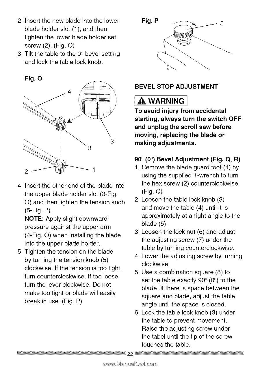
2. Insert the new blade into the lower blade holder slot (1), and then tighten the lower blade holder set screw (2). (Fig. O) 3. Tilt the table to the 0° bevel setting and lock the table lock knob. Fig. P Fig. O BEVEL STOP ADJUSTMENT I_ WARNING I To avoid injury from accidental starting, always turn the switch OFF and unplug the scroll saw before moving, replacing the blade or 3 making adjustments. 2 4. Insert the other end of the blade into the upper blade holder slot (3-Fig. O) and then tighten the tension knob (5-Fig. P). NOTE: Apply slight downward pressure against the upper arm (4-Fig. O) when installing the blade into the upper blade holder. 5. Tighten the tension on the blade by turning the tension knob (5) clockwise. If the tension is too tight, turn counterclockwise. If too loose, turn the lever clockwise. Do not make too tight or blade will easily break in use. (Fig. P) 900 (0 °) Bevel Adjustment (Fig. Q, R) 1. Remove the blade guard foot (1) by using the supplied T-wrench to turn the hex screw (2) counterclockwise. (Fig. Q) 2. Loosen the table lock knob (3) and move the table (4) until it is approximately at a right angle to the blade (5). 3. Loosen the lock nut (6) and adjust the adjusting screw (7) under the table by turning counterclockwise. 4. Lower the adjusting screw by turning clockwise. 5. Use a combination square (8) to set the table exactly 90 o (0°) to the blade. If there is space between the square and blade, adjust the table angle until the space is closed. 6. Lock the table lock knob (3) under the table to prevent movement. Raise the adjusting screw under the tabel until the tip of the screw touches the table.
-
 1
1 -
2
-
3
-
4
-
5
-
6
-
7
-
8
-
9
-
10
-
11
-
12
-
13
-
14
-
15
-
16
-
 17
17 -
 18
18 -
 19
19 -
 20
20 -
 21
21 -
 22
22 -
 23
23 -
 24
24 -
 25
25 -
 26
26 -
 27
27 -
28
-
29
-
30
-
31
-
32
-
33
-
34
-
35
-
36
 |
 |