Craftsman 21914 Operation Manual - Page 11
Drill, Press - drill press manual
 |
View all Craftsman 21914 manuals
Add to My Manuals
Save this manual to your list of manuals |
Page 11 highlights
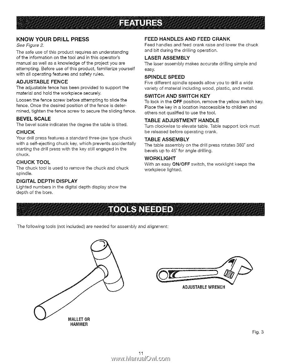
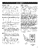
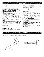
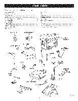
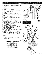
KNOW YOUR DRILL PRESS See Figure 2. The safe use of this product requires an understanding of the information on the tool and in this operator's manual as well as a knowledge of the project you are attempting. Before use of this product, familiarize yourself with all operating features and safety rules. ADJUSTABLE FENCE The adjustable fence has been provided to support the material and hold the workpiece securely. Loosen the fence screw before attempting to slide the fence. Once the desired position of the fence is determined, tighten the fence screw to secure the sliding fence. BEVEL SCALE The bevel scale indicates the degree the table is tilted. CHUCK Your drill press features a standard three-jaw type chuck with a self-ejecting chuck key, which prevents accidentally starting the drill press with the key still engaged in the chuck. CHUCK TOOL The chuck tool is used to remove the chuck and chuck spindle. DIGITAL DEPTH DISPLAY Lighted numbers in the digital depth display show the depth of the bore. FEED HANDLES AND FEED CRANK Feed handles and feed crank raise and lower the chuck and bit during the drilling operation. LASER ASSEMBLY The laser assembly makes accurate drilling simple and easy. SPINDLE SPEED Five different spindle speeds allow you to drill a wide variety of material including wood, plastic, and metal. SWITCH AND SWITCH KEY To lock in the OFF position, remove the yellow switch key. Place the key in a location inaccessible to children and others not qualified to use the tool. TABLE ADJUSTMENT HANDLE Turn clockwise to elevate table. Table support lock must be released before operating crank. TABLE ASSEMBLY The table assembly on the drill press rotates 360 ° and bevels up to 45 ° for angle drilling. WORKMGHT With an easy ON/OFF switch, the worklight keeps the workpiece lighted. The following tools (not included) are needed for assembly and alignment: MALLET OR HAMMER ADJUSTAgLEWRENCH Fig. 3 11
-
 1
1 -
2
-
3
-
4
-
5
-
 6
6 -
 7
7 -
 8
8 -
 9
9 -
 10
10 -
 11
11 -
 12
12 -
 13
13 -
 14
14 -
 15
15 -
 16
16 -
17
-
18
-
19
-
20
-
21
-
22
-
23
-
24
-
25
 |
 |