Craftsman 21914 Operation Manual - Page 19
Tablerotation
 |
View all Craftsman 21914 manuals
Add to My Manuals
Save this manual to your list of manuals |
Page 19 highlights
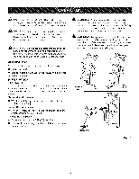
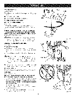
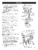
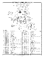
TABLEROTATION See Figure 17. The table can be rotated out of the way when drilling large objects. [] Loosen the table lock handle. [] Rotate the table to the desired position. [] Retighten the table lock handle. SELF-EJECTING CHUCK KEY See Figure 18. The self-ejecting chuck key ensures the chuck key is removed from the chuck before the drill press is turned On. In order to loosen or tighten the chuck using the chuck key, push the key into the key hole located on the chuck. Rotate the key clockwise to tighten the chuck or counterclockwise to loosen the chuck. _, WARNING: Use only the self-ejecting chuck key provided. Always remove chuck key. Failure to heed this warning could result in serious personal injury. iNSTALLiNG AND REMOVING BITS See Figure 19. [] Unplug the drill press. [] Open or close the chuck jaws to a point where the opening is slightly larger than the bit size you intend to use. [] Insert drill bit into the chuck the full length of the jaws. LOCK HANDLE CHUCK KEY _ WARNING: Do not insert drill bit into chuck jaws and tighten as shown in figure 19. This could cause drill bit to be thrown from the drill press, resulting in possible serious personal injury or damage to the chuck. [] Tighten chuck jaws securely using chuck key provided. Do not use a wrench to tighten or loosen chuck jaws. [] Remove chuck key. [] To remove the drill bit, reverse the steps listed above. DRiLLiNG See Figures 20 - 21. NOTE: Before beginning any drilling operation, position the worklight for maximum lighting of the workpiece. Using a C-clamp or similar clamping device, secure the workpiece to the work table. To protect the surface of the workpiece, use a piece of scrap between the clamp and the workpiece. D Select the proper drill bit based on the hole size desired. For large holes, drill a pilot hole first, using a smaller diameter bit. D Set table assembly to desired height. If desired, set feed shaft at desired spindle depth. 19 KEYHOLE WRONG TABLE Fig. 17 Fig. 18 Fig. 19
-
 1
1 -
2
-
3
-
4
-
5
-
6
-
7
-
8
-
9
-
10
-
11
-
12
-
13
-
 14
14 -
 15
15 -
 16
16 -
 17
17 -
 18
18 -
 19
19 -
 20
20 -
 21
21 -
 22
22 -
 23
23 -
 24
24 -
25
 |
 |