Craftsman 21914 Operation Manual - Page 16
Ifrem, t, saport.re
 |
View all Craftsman 21914 manuals
Add to My Manuals
Save this manual to your list of manuals |
Page 16 highlights
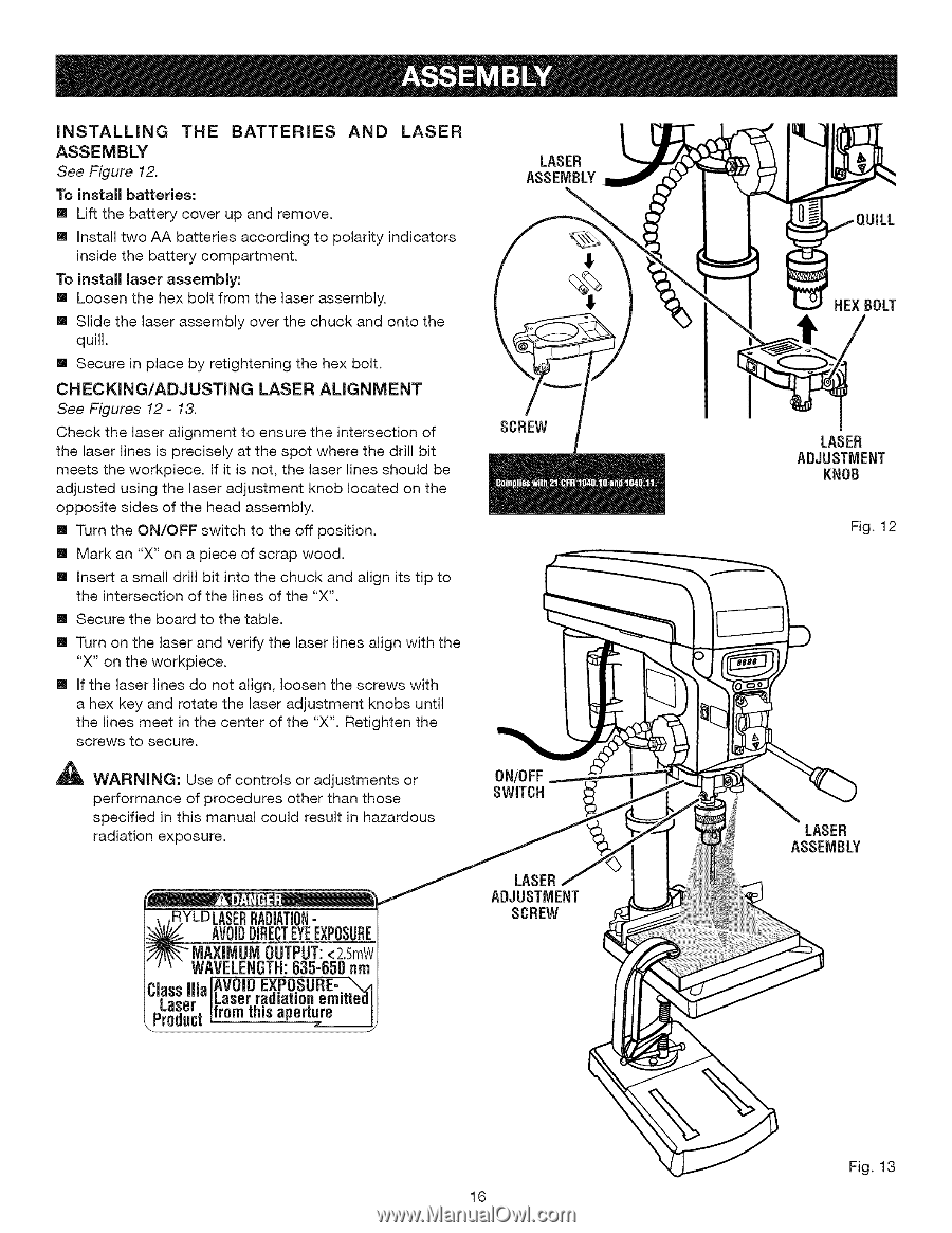
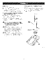
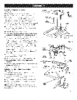
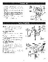
INSTALLING THE BATTERIES ASSEMBLY See Figure 12. To install batteries: [] Lift the battery cover up and remove. AND LASER [] Install two AA batteries according to polarity indicators inside the battery compartment. To install laser assembly: [] Loosen the hex bolt from the laser assembly. [] Slide the laser assembly over the chuck and onto the quill. [] Secure in place by retightening the hex bolt. CHECKiNG/ADJUSTING LASER ALIGNMENT See Figures 12- 13. Check the laser alignment to ensure the intersection of the laser lines is precisely at the spot where the drill bit meets the workpiece. If it is not, the laser lines should be adjusted using the laser adjustment knob located on the opposite sides of the head assembly. [] Turn the ON/OFF switch to the off position. [] Mark an "X" on a piece of scrap wood. [] Insert a small drill bit into the chuck and align its tip to the intersection of the lines of the "X". [] Secure the board to the table. [] Turn on the laser and verify the laser lines align with the "X" on the workpiece. [] If the laser lines do not align, loosen the screws with a hex key and rotate the laser adjustment knobs until the lines meet in the center of the "X". Retighten the screws to secure. _ WARNING: Use of controls or adjustments or performance of procedures other than those specified in this manual could result in hazardous radiation exposure. LASER ASSEMBLY SCREW ON/OFF SWITCH ;ERRADiATIO- H AVOIDIRECETYEEXPOSURE "MAXIMUM OUTPUT
-
 1
1 -
2
-
3
-
4
-
5
-
6
-
7
-
8
-
9
-
10
-
 11
11 -
 12
12 -
 13
13 -
 14
14 -
 15
15 -
 16
16 -
 17
17 -
 18
18 -
 19
19 -
 20
20 -
 21
21 -
22
-
23
-
24
-
25
 |
 |