Craftsman 88733 Operation Manual - Page 18
Replacing, Shield, Servicing, Cutting, Blades
 |
UPC - 071887330009
View all Craftsman 88733 manuals
Add to My Manuals
Save this manual to your list of manuals |
Page 18 highlights
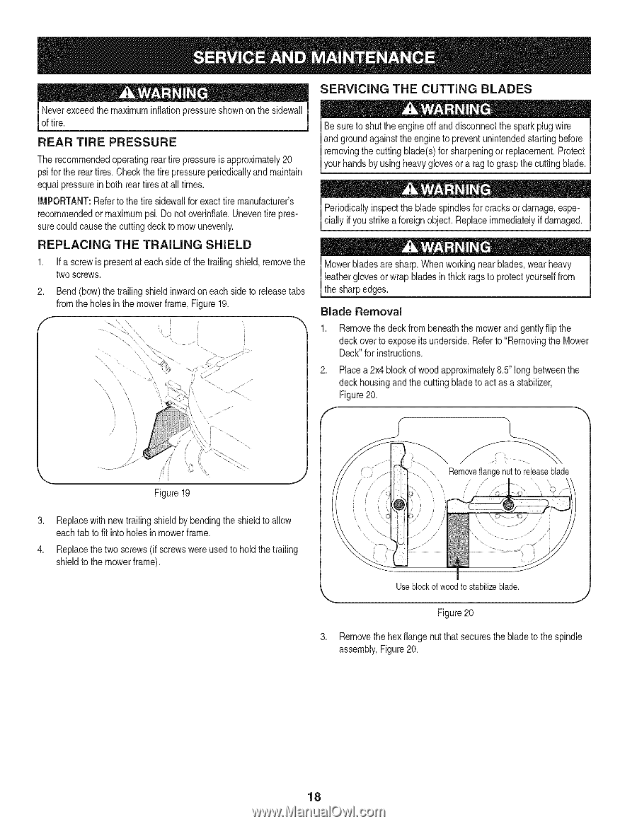
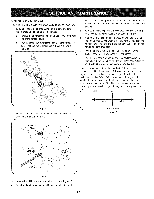
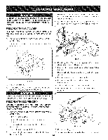
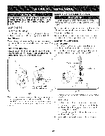
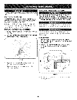
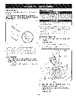
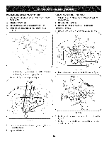
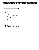
SERVICING THE CUTTING BLADES Neverexceedthe maximuminflationpressureshownon the sidewall of tire. REAR TIRE PRESSURE The recommendedoperatingreartire pressureisapproximately20 psi forthe reartires.Checkthe tire pressureperiodicallyand maintain equal pressurein bothrear tiresat all times. IMPORTANT:Referto the tire sidewallfor exacttire manufacturer's recommendedor maximumpsi. Do notoverinflate.Uneventire pressurecouldcausethe cuttingdeck to mow unevenly. REPLACING THE TRAILING SHIELD If a screwis presentat each sideof the trailingshield,removethe two screws. . Bend (bow)the trailingshieldinwardon eachside to releasetabs fromthe holesin the mowerframe,Figure19. Be sureto shut the engineoff and disconnectthe sparkplug wire and groundagainst theengineto preventunintendedstartingbefore removingthecutting blade(s)for sharpeningor replacement.Protect yourhandsby usingheavyglovesor a ragto graspthe cuttingblade. Periodicallyinspectthe blade spindlesfor cracks or damage,especially if you strikea foreignobject.Replaceimmediatelyif damaged. Mowerbladesare sharp.Whenworkingnearblades,wearheavy leatherglovesor wrap bladesin thick ragsto protectyourselffrom the sharpedges. Blade Removal Removethe deck from beneaththe mowerand gentlyflip the deck overto exposeits underside.Referto "Removingthe Mower Deck"for instructions. . Placea 2x4 blockof woodapproximately8.5"long betweenthe deck housingand the cuttingblade to act as a stabilizer, Figure20. F \ \_ ii Figure19 Removfelangenutto releaseblade . Replacewith newtrailingshieldbybendingthe shieldto allow eachtab to fit intoholesin mowerframe. . Replacethe two screws(if screwswere usedto hold thetrailing shieldto the mowerframe). Useblockofwoodtostabilizeblade. J Figure20 3. Removethe hexflangenut that securesthe bladeto the spindle assembly,Figure20. 18
-
 1
1 -
2
-
3
-
4
-
5
-
6
-
7
-
8
-
9
-
10
-
11
-
12
-
 13
13 -
 14
14 -
 15
15 -
 16
16 -
 17
17 -
 18
18 -
 19
19 -
 20
20 -
 21
21 -
 22
22 -
 23
23 -
24
-
25
-
26
-
27
-
28
-
29
-
30
-
31
-
32
-
33
-
34
-
35
-
36
-
37
-
38
-
39
-
40
-
41
-
42
-
43
-
44
-
45
-
46
-
47
-
48
-
49
-
50
-
51
-
52
-
53
-
54
-
55
-
56
-
57
-
58
-
59
-
60
-
61
-
62
-
63
-
64
-
65
-
66
-
67
-
68
-
69
-
70
-
71
-
72
 |
 |