Cub Cadet Challenger MX 550 Yellow Operation Manual - Page 18
Cleaning Primary Air Filter Element, Cleaning the Air Intake
 |
View all Cub Cadet Challenger MX 550 Yellow manuals
Add to My Manuals
Save this manual to your list of manuals |
Page 18 highlights
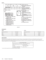
2. Remove the bleeder screw (a) on the radiator, fill the radiator and when fluid begins to come out of the bleeder screw hole, replace the bleeder screw (a). The bleeder screw (a) can be accessed via the front right wheel well. See Figure 5-25. (a) Cleaning Primary Air Filter Element Open the air cleaner cover once a week under ordinary conditions - or daily when used in a dusty place - to get rid of large particles of dust and dirt. Note: Do not run the engine with filter element removed. 1. Remove the air filter access panel. 2. Remove the air filter cover (a) from the three air filter cover holders (b). See Figure 5-27. (b) (b) 9. Install the air filter case cover and be sure the crankcase breather hose is connected. Note: Be sure to refit the air filter cover with the arrow (on the rear of air filter cover) upright. If the air filter cover is improperly fitted the evacuator valve will not function and dust will adhere to the air filter element. Cleaning the Air Intake Air Intake Screen 1. Remove the hood and locate the air intake. 2. Remove the rubber seal (b) around the front of the air intake (a) and remove the air intake screen (c). See Figure 5-30. (a) (a) Figure 5-25 3. Start the utility vehicle and let it idle. 4. Remove the second bleeder screw (a) where the radiator hose (b) connects to the engine and let the engine run until a steady stream of fluid comes out of the bleeder screw (a) hole indicating there are no more air pockets in the coolant system. Replace the bleeder screw (a). See Figure 5-26. (a) (b) Figure 5-26 5. Top off the radiator and replace the radiator cap. Then lower the front of the utility vehicle off the jack. (b) Figure 5-27 3. Remove the air filter element. See Figure 5-28. Figure 5-28 4. Remove the inner filter (a) from the paper element (b). See Figure 5-29. (b) (a) (b) (c) Figure 5-30 3. Rinse the air intake screen (c) with water and replace the air intake screen (c) and rubber seal (b). See Figure 5-30. Drain the Air Intake 1. Remove the nine Allen-head bolts (a) and washers (a) securing the middle skid plate to the bottom of the utility vehicle. See Figure 5-31. (a) (a) (a) (a) (a) (a) (a) (a) (a) Figure 5-31 18 Section 5 - Product Care Figure 5-29 5. Clean the paper element with a soft brush or low pressure air. Be careful not to damage the paper pleats during cleaning. 6. Inspect the inner filter for deposits or damage. 7. If either filter are excessively dirty or damaged, replace filters as a set. 8. Re-install the primary air filter element.
-
 1
1 -
2
-
3
-
4
-
5
-
6
-
7
-
8
-
9
-
10
-
11
-
12
-
 13
13 -
 14
14 -
 15
15 -
 16
16 -
 17
17 -
 18
18 -
 19
19 -
 20
20 -
 21
21 -
 22
22 -
 23
23 -
24
 |
 |
