Cub Cadet Challenger MX 550 Yellow Operation Manual - Page 22
Traveling Speeds, 550UTV, 750UTV, Vehicle Limitations, Fuse Box
 |
View all Cub Cadet Challenger MX 550 Yellow manuals
Add to My Manuals
Save this manual to your list of manuals |
Page 22 highlights
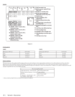
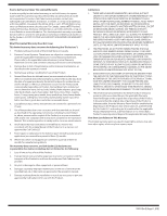
Fuse Box K1 K2 K3 K4 F1 F2 F3 F4 F7 F8 F9 F10 F13 F14 SpSapraere ffuussee 20A 10A 5A 30A 10A 5A K1:MODEL: HFV11 12-H-R ( DG ) Fuel pump relay K2:MODEL: HFV11 12-H-R ( DG ) Neutral start relay K3:MODEL: HFV11 12-H-R ( DG ) Ignition switch relay K4:MODEL: HFV9 012-1ZR All-wheel-drive relay K5:MODEL: HFV9 012-1ZR Differential relay K5 F1 20A Fan motor fuse F2 5A Fan control system/Pump relay fuse F5 F6 F3 5A Winch controller fuse F4 5A The four-wheel drive F11 F12 differential control relay fuse OUT Flasher F5 10A DC fuse F6 10A Pump/Meter, ECU switch fuse F7 10A Horn/Neutral start relay fuse F8 5A Signal light system/Neutral start relay fuse F9 5A Speed limiter/EPS controller fuse F10 10A Rear axle differential fuse F11 10A Headlight fuse F12 5A Meter, ECU energize fuse F13 30A Standby connection post fuse F14 30A Eps motor fuse Traveling Speeds 550UTV Range gear shift lever Low High Reverse Figure 6-1 km/h (mph) 54.9 (34.1) 64.9 (40.3) 20.9 (13.0) 750UTV Range gear shift lever Low High Reverse km/h (mph) 57 (35.4) 80 (49.7) 40 (24.8) Vehicle Limitations The Vehicle has been thoroughly tested for proper performance with implements sold or approved by manufacturer. Use with implements which are not sold or approved and which exceed the maximum specifications listed below, or which are otherwise unfit for use, on this vehicle may result in vehicle malfunction or failures with a possibility of vehicle damage, property damage and injury to the operator or others. Any malfunctions or failures of the vehicle resulting from use with improper implements are not covered by the warranty. Max cargo loading weight Cargo Bed Capacity = 227 kg (500 lb) Max. rolling weight trailer Vehicle Total Load Capacity = 453.5 kg (1000 lb) * (Operator + one passenger + opt + acc) weight + trailer weight 544kg (1200 lbs.) Max. tongue weight 50 kg (110 lbs.) 1. Above mentioned specifications are based on level ground condition. 22 Section 6 - Specifications
-
 1
1 -
2
-
3
-
4
-
5
-
6
-
7
-
8
-
9
-
10
-
11
-
12
-
13
-
14
-
15
-
16
-
 17
17 -
 18
18 -
 19
19 -
 20
20 -
 21
21 -
 22
22 -
 23
23 -
 24
24
 |
 |
