Cub Cadet PRO Z 160S KW Owners Manual - Page 22
Charging the Battery, Servicing Electrical System, Relays and Switches, Deck Removal, Deck
 |
View all Cub Cadet PRO Z 160S KW manuals
Add to My Manuals
Save this manual to your list of manuals |
Page 22 highlights
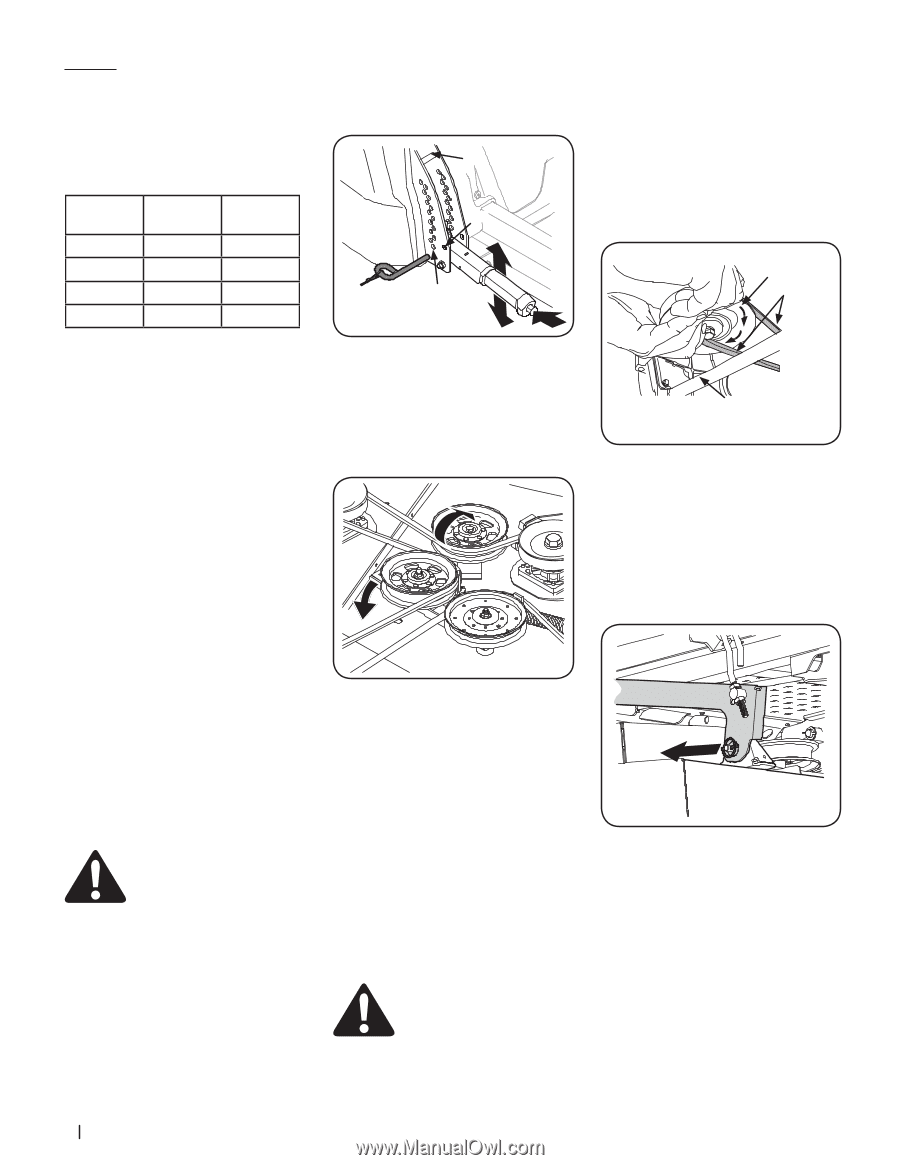
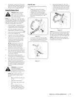
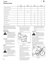
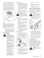
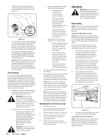
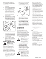
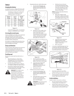
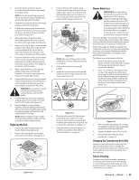
Service Charging the Battery Test and, if necessary, recharge the battery after the tractor has been stored for a period of time. • A voltmeter or load tester should read 12.6 volts (DC) or higher across the battery terminals. See Figure 4-1. Voltmeter Reading 12.7 12.4 12.2 12.0 State of Charge 100% 75% 50% 25% Charging Time Full Charge 90 Min. 180 Min. 280 Min. Figure 4-1 • Charge the battery with a 12-volt battery charger at a MAXIMUM rate of 10 amps. Servicing Electrical System A fuse is installed to protect the tractor's electrical system from damage caused by excessive amperage. Always use the same capacity fuse for replacement. If the electrical system does not function, check for a blown fuse. If you have a recurring problem with blown fuses, have the tractor's electrical system checked by your Cub Cadet Service Dealer. Relays and Switches There are several safety switches in the electrical system. If a function of the safety interlock system described earlier is not functioning properly, have the electrical system checked by your Cub Cadet Service Dealer. Deck Removal Remove the mower deck from the tractor as follows: 1. Move the tractor to a level surface, disengage the PTO, stop the engine place the control levers in the neutral/ parking brake engaged position. 2. Move the deck gauge wheels or rollers to their highest setting (lowest deck setting). 3. Remove the 'V' belt from the PTO pulley, located on the bottom of the engine, using one of the following two methods. WARNING! The muffler at the rear of the tractor may be extremely hot, and could cause serious burns. Use extreme caution when near the muffler. Allow the muffler to fully cool before removing the belt from the PTO pulley. 4. Releasing belt tension with the idler pulley: a. Using the deck lift handle, raise the deck to the DECK REMOVAL/ INSTALLATION POSITION (a). See Figure 4-2. (b) (a) (c) Figure 4-2 b. Working from the middle of the tractor, pivot the idler bracket and movable idler pulley rearward away from the backside of the 'V" belt (a) just far enough to lift the belt up and over the idler pulley (b). See Figure 4-3. (b) (a) Figure 4-3 c. From beneath the rear of the tractor, slide the belt off of the PTO pulley on the bottom of the engine. d. Lower the deck into the DECK REMOVAL/INSTALLATION POSITION (a) using the deck lift handle. See Figure 4-2. e. Skip ahead to step 6. 5. Rolling the belt off the PTO pulley: a. Using the deck lift handle, raise the deck to the DECK REMOVAL/ INSTALLATION POSITION (a). See Figure 4-3. b. Sitting behind the tractor facing forward, reach beneath the tractor to grasp the belt at the front of the PTO pulley. WARNING! Use caution to avoid pinching your fingers when rolling the belt off the PTO pulley. c. Pull the left side of the belt rearward and downward while manually turning the PTO pulley to the right until the belt rides out onto the edge of the lower sheave of the pulley. NOTE: If pulling the right side of the belt, turn the pulley left. d. While still holding the belt downward, continue turning the PTO pulley until the belt is rolled off the pulley. Refer to Figure 4-4. PTO Pulley PTO Belt Transmission Tube Figure 4-4 e. Lower the deck into the DECK REMOVAL/INSTALLATION POSITION (a) using the deck lift handle. See Figure 4-2. f. Move on to step 6. 6. Locate the LH and RH deck release pins (a) on each side of the deck. Pull the release pins outward and release the deck from the LH and RH deck lift arms. See Figure 4-5. (a) Figure 4-5 7. Slide the front deck lift rod off the hanger brackets on the front of the deck 8. Place the deck lift handle into the highest mowing position and slide the deck out from the right side of the tractor. Deck Installation Install the deck on the tractor as follows: 1. Place the deck lift handle in the highest mowing position (b). See Figure 4-2. 2. Slide the deck under the tractor on the right side of the tractor lining up the deck hanger brackets and the deck lift arms. 22 Section 4- Service
-
 1
1 -
2
-
3
-
4
-
5
-
6
-
7
-
8
-
9
-
10
-
11
-
12
-
13
-
14
-
15
-
16
-
 17
17 -
 18
18 -
 19
19 -
 20
20 -
 21
21 -
 22
22 -
 23
23 -
 24
24 -
 25
25 -
 26
26 -
 27
27 -
28
 |
 |