Cub Cadet PRO Z 972 SDL Operation Manual - Page 10
Seat Adjustment
 |
View all Cub Cadet PRO Z 972 SDL manuals
Add to My Manuals
Save this manual to your list of manuals |
Page 10 highlights
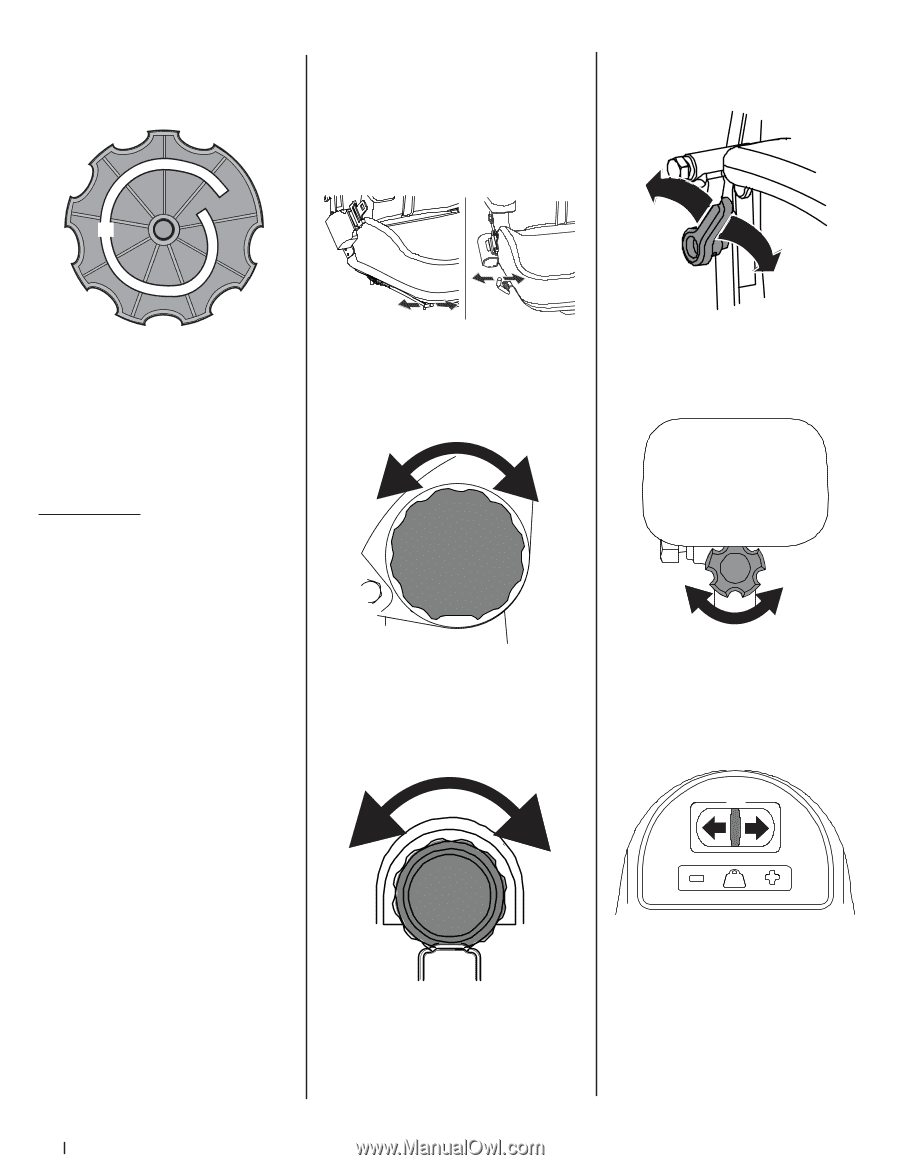
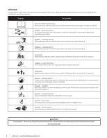
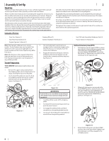
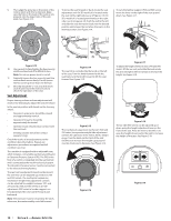
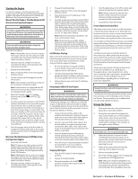
9. Then align the spiral (a) on the inside of the recliner knob with the recliner pin. Make sure the hub on the back of the recliner sits properly into the large holes of the side plate. See Figure 2-13. To move the seat forward or back, locate the seat adjustment rod. On SD models it is located under the seat on the right side (see a in Figure 2-14). On SDL models it is located prominently on the right side ( see b in Figure 2-14). Push the rod to the left and slide the seat forward or back into the desired position and release the rod when the seat is in the desired position. See Figure 2-14. To vary the lumbar support (700 and 900 series) move the lever on the right of the seat up and down. See Figure 2-17. (a) (a) (b) Figure 2-13 10. Use a wrench to hand tighten the hex screw (g) until the recliner knob (f) is difficult to turn. Note: Do not use power tools to install. 11. Gradually loosen the hex screw (g) until the recliner knob moves freely. Do not loosen the hex screw (g) more than one full turn. 12. Securely install the 1/4" nut onto the clinchstud (h) and rotate the recliner knob to check the operation of the seat. Seat Adjustment Proper steering column and seat adjustment will result in the following (to adjust the seat see below): In the neutral position with hands on the steering wheel, • Operator's upper arms should be relaxed and approximately vertical. • Operator's forearms should be approximately horizontal. • Operator's back should stay in contact with the seat back. • Steering column should not contact operator's legs. Check the results of any adjustments to the conditions described above. Repeat any adjustment procedures as required until all conditions are met. This machine is equipped with an adjustable seat, which includes a retractable seat belt assembly and an Operator Presence Sensor (OPS). The OPS in the form of a switch, is integrated into the seat bottom and is connected to the machine electrical system. The Operator Presence Sensor must be connected to the electrical wiring harness. The seat can be adjusted forward and backward, the armrests can be adjusted up and down (700 and 900 series) , the mechanical suspension mechanism weight/ride adjustment controls can be adjusted for weights between 125- and 275-pounds (500 and 700 series) or air ride adjustment (900 series), a lumbar support can be adjusted and the seat can tilt forward and backward. Note: The seat base must be secured by the latch, otherwise, the seat assembly could tilt forward. Figure 2-14 The seat tilt is controlled by the knob on the left of the seat. Turn the knob rearward to tilt the seat back, turn the knob forward to tilt the seat forward. See Figure 2-15. Figure 2-15 The mechanical suspension mechanism (500 and 700 series) incorporates weight/ride adjustment controls for operators in the 100 to 280 lb. weight range. Turn the knob on the front of the seat clockwise to increase the weight capacity and counter-clockwise to decrease. See Figure 2-16. Figure 2-16 Figure 2-17 To adjust the height of the arm rests (700 and 900 series) , lift the arm rest and rotate the knob under the arm rest right or left to increase or decrease the height. See Figure 2-18. Figure 2-18 The air ride (900 series) can be adjusted up or down using the height adjustment lever on the front of the seat. Press the lever to the left (+) to raise the height of seat and to the right (-) to lower the height of the seat. See Figure 2-19. (a) Figure 2-19 10 Section 2 - Assembly & Set-Up
-
 1
1 -
2
-
3
-
4
-
 5
5 -
 6
6 -
 7
7 -
 8
8 -
 9
9 -
 10
10 -
 11
11 -
 12
12 -
 13
13 -
 14
14 -
 15
15 -
16
-
17
-
18
-
19
-
20
-
21
-
22
-
23
-
24
-
25
-
26
-
27
-
28
-
29
-
30
-
31
-
32
 |
 |