Cub Cadet PRO Z 972 SDL Operation Manual - Page 26
Replacing the Blades, Sharpening the Blades, Changing the Spindle Assembly
 |
View all Cub Cadet PRO Z 972 SDL manuals
Add to My Manuals
Save this manual to your list of manuals |
Page 26 highlights
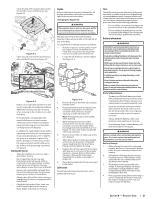
4. The speed nut should hold the carriage screw (c) and tab bolt in place, if not re-install as shown in Figure 4-23. 5. Using a 1⁄2" drive insert the end into the 1⁄2" square opening in the deck idler assembly (a) and rotate the deck idler assembly (a) clockwise. See Figure 4-24. While holding the deck idler assembly (a), loosen the deck belt from the pulley and slide the belt away from the pulley. 2. Remove the flange lock nut (a) and flat washer (b) from the spindle shaft, and remove the blade (c). See Figure 4-26. (a) (b) (c) 2. Clean any debris from the blades. Keep blades sharp and free of build up at all times. 3. To properly sharpen the cutting blades, remove equal amounts of metal from both ends of the blades along the cutting edges, parallel to the trailing edge, at a 25°-30° angle. Always grind each cutting blade edge equally to maintain proper blade balance. See Figure 4-28. (a) Figure 4-24 WARNING Avoid pinching injuries. Never place your fingers on the idler spring or between the belt and a pulley while removing the belt. 6. Route the new belt as shown in Figure 4-24. Then reinstall the deck and PTO belt. Replacing the Blades WARNING Before performing any maintenance, disengage the PTO, engage the parking brake lever, turn the ignition key to the "OFF" position and remove the key from the switch. Protect your hands by using heavy gloves when handling the blades. When servicing the mower deck, be careful not to cut yourself on the sharpened blades. 1. Remove the deck as instructed in the Deck Removal section on page 24. 2. For easier access, flip the deck over, then jack up the front of the deck about one foot and block it in that position. To remove the blade: 1. Secure the blade from turning counter clockwise during service by placing a block of wood between the blade and the deck housing, see Figure 4-25, or wrap a rag around around one end of the blade and grasp the blade firmly. Figure 4-25 Figure 4-26 To replace or reinstall the blade: 1. Add a small amount of multi-purpose grease to the spindle shaft threads to avoid corrosion and galvanic action. 2. Put the blade in place on the spindle shaft. Be sure to install the blade with the side marked "Bottom", "Grass Side" or with a part number stamped facing the ground when the deck is reinstalled on the tractor and in the operating position. 3. Carefully place the flat washer on the spindle shaft. Be sure that the splines at the base of the spindle shaft threads line up with the washer splines. See Figure 4-27. Figure 4-27 4. Secure the blade from turning clockwise when reinstalling the flange lock nut (the opposite direction of blade removal). 5. Install the flange lock nut onto the spindle shaft over the blade and flat washer. Torque to 100-130 ft-lbs (136-176 N-m). WARNING Never mow with dull blades. Blades that are bent should be replaced. The cutting blades are sharp and can cause severe injury. Wrap the cutting surface of the blade with a rag to avoid injury. Sharpening the Blades 1. Set the parking brake. Figure 4-28 WARNING If a blade is bent or otherwise damaged, replace the blade with a new one. Use only original equipment blades. WARNING A poorly balanced blade will cause excessive vibration, may damage the machine and/or result in personal injury. 6. Test the blade's balance using a blade balancer. Grind metal from the heavy side until it balances evenly. Note: When replacing the blade, be sure to install the blade with the side of the blade marked ''Bottom'' or "Grass Side" (or with a part number stamped in it) facing the ground when the mower is in the operating position. WARNING Use a torque wrench to tighten the blade spindle hex flange nut to between 100 lbs-ft and 130 lbs-ft. Changing the Spindle Assembly 1. Remove the deck as instructed in the Deck Removal section on page 24. 2. Jack up the front of the mowing deck about one foot and block it in that position. 3. Remove the deck cover. 4. Remove the drive belts. See Replacing the Deck belt on page 24. 5. Remove the blade. See Replacing the Blades on page 25. 26 Section 4- Product Care
-
 1
1 -
2
-
3
-
4
-
5
-
6
-
7
-
8
-
9
-
10
-
11
-
12
-
13
-
14
-
15
-
16
-
17
-
18
-
19
-
20
-
 21
21 -
 22
22 -
 23
23 -
 24
24 -
 25
25 -
 26
26 -
 27
27 -
 28
28 -
 29
29 -
 30
30 -
 31
31 -
32
 |
 |
