Cub Cadet SC 500 EQ Operation Manual - Page 12
Adjustments
 |
View all Cub Cadet SC 500 EQ manuals
Add to My Manuals
Save this manual to your list of manuals |
Page 12 highlights
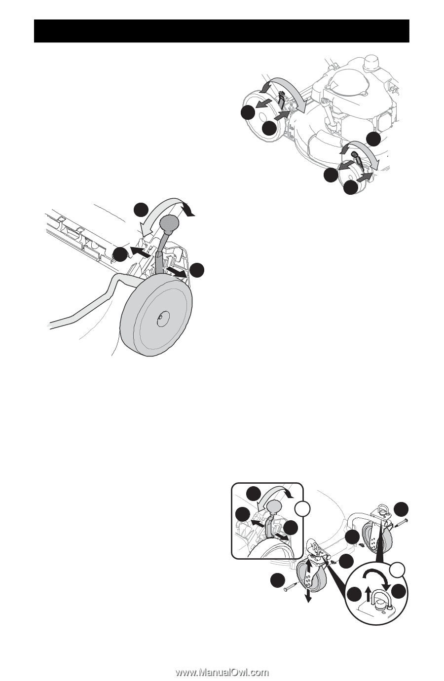
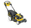
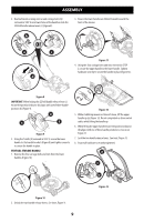
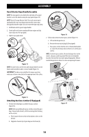
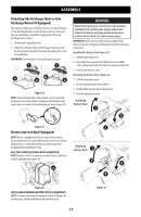
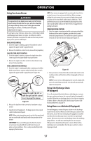
ADJUSTMENTS Cutting Height Adjustments This mower is equipped with one of three types of cutting height adjustment. Refer to Single Lever, Dual Lever or Rear Wheel/ Caster Wheels in this section. SINGLE LEVER The single lever cutting height adjustment is located above the rear left wheel (Figure 22). 1. Carefully pull the height adjustment lever outward towards wheel (mower will tend to fall when lever is moved outward). 2. Move lever to desired position for a change in cutting height. 3. Release lever towards deck. 2 Higher Lower 3 1 Figure 22 DUAL LEVER Front Wheel Drive Mowers - The dual lever cutting height adjustment levers are located above the front and rear right wheels. Rear Wheel Drive Mowers - The dual lever cutting height adjustment levers are located above the front and rear left wheels. NOTE: Front wheel drive mower shown in Figure 23. NOTE: On select mowers - The front and rear height adjustment levers move in the opposite direction to adjust height. 1. Carefully pull the height adjustment lever outward towards wheel (mower will tend to fall when lever is moved outward). 2. Move lever to desired position for a change in cutting height. 3. Release lever towards deck. IMPORTANT: All wheels must be placed in the same position. For rough or uneven lawns, move each height adjustment lever to a higher position. This will prevent you from cutting the grass too close to the ground. Higher 1 Lower 3 2 Higher NOTE: Front wheel drive mower shown. 1 3 Lower Figure 23 REAR WHEEL/CASTER WHEELS NOTE: The rear wheel cutting height adjustment lever is located above the rear left wheel (Inset A, Figure 24). 1. Pull lever out and away from mower. 2. Move lever forward or back for desired cutting height. 3. Release lever towards mower deck. NOTE: The caster wheels cutting height are determined by selecting one of six positions on each caster assembly (Figure 24). 4. Remove wing nut (a) from axle bolt (b). Slide axle bolt from the assembly and select a cutting height. 5. Reinsert axle bolt in the square hole desired through wheel assembly and secure with wing nut removed in STEP 1. IMPORTANT: All wheels must be placed in the same relative position. For rough or uneven lawns, move the height adjustment lever to a higher position. This will stop scalping of grass. 6. The casters can be locked in a straight ahead position or positioned to swivel freely (Inset B, Figure 24). a. Lift lock pins. b. Place in larger holes to lock wheels. Place pins in smaller holes to allow casters to rotate freely for turning. 2 3 A b 1 a a B b 1 2 Figure 24 12
-
 1
1 -
2
-
3
-
4
-
5
-
6
-
 7
7 -
 8
8 -
 9
9 -
 10
10 -
 11
11 -
 12
12 -
 13
13 -
 14
14 -
 15
15 -
 16
16 -
 17
17 -
18
-
19
-
20
-
21
-
22
-
23
-
24
-
25
-
26
-
27
-
28
-
29
-
30
-
31
-
32
-
33
-
34
-
35
-
36
-
37
-
38
-
39
-
40
-
41
-
42
-
43
-
44
-
45
-
46
-
47
-
48
-
49
-
50
-
51
-
52
-
53
-
54
-
55
-
56
-
57
-
58
-
59
-
60
-
61
-
62
-
63
-
64
-
65
-
66
-
67
-
68
-
69
-
70
-
71
-
72
 |
 |