Cub Cadet SC 500 EQ Operation Manual - Page 8
Cub Cadet SC 500 EQ Manual
 |
View all Cub Cadet SC 500 EQ manuals
Add to My Manuals
Save this manual to your list of manuals |
Page 8 highlights
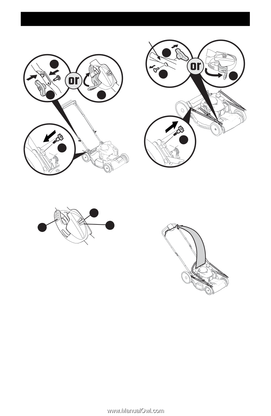
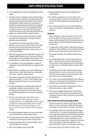
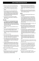
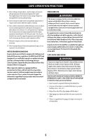
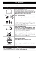
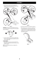
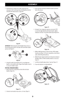
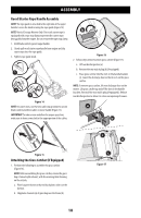
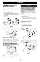
ASSEMBLY 5. Reattach knobs or wing nuts (a) and carriage bolts (b) removed in STEP 2 into lower holes of the handle or lock the EZ-fold handle release levers (c) (Figure 4). b Do not loosen or remove hex head screws. a b c a c d d Figure 4 IMPORTANT: When locking the EZ-fold handle release lever (c) ensure the position indicator (h) aligns with one of three handle positions (i) (Figure 5). h c i Figure 6 2. Remove the T-bolts (d) from the handle brackets (Figure 6). 3. While stabilizing mower so it doesn't move, gently lift and pivot the upper handle into the operating position (Figure 7). Make certain the lower handle is seated securely into the handle brackets. Do not crimp blade or drive control cables while lifting the handle up Figure 5 6. Insert the T-bolts (d) removed in STEP 4 through the handle brackets and lower handle (Figure 4) and tighten securely to secure the handle in place. FOLDING HANDLE 1. Remove knobs or wing nuts (a) and carriage bolts (b) from the handle or if equipped with the EZ-lock handle (c), proceed to STEP 2 (Figure 6). NOTE: The EZ-Fold handle release levers are shipped in the unlocked position. Figure 7 8
-
 1
1 -
2
-
 3
3 -
 4
4 -
 5
5 -
 6
6 -
 7
7 -
 8
8 -
 9
9 -
 10
10 -
 11
11 -
 12
12 -
 13
13 -
14
-
15
-
16
-
17
-
18
-
19
-
20
-
21
-
22
-
23
-
24
-
25
-
26
-
27
-
28
-
29
-
30
-
31
-
32
-
33
-
34
-
35
-
36
-
37
-
38
-
39
-
40
-
41
-
42
-
43
-
44
-
45
-
46
-
47
-
48
-
49
-
50
-
51
-
52
-
53
-
54
-
55
-
56
-
57
-
58
-
59
-
60
-
61
-
62
-
63
-
64
-
65
-
66
-
67
-
68
-
69
-
70
-
71
-
72
 |
 |