Cub Cadet Z-Force 48 Z-Force 48 Operator's Manual - Page 28
Adjusting the Belt Tension, Brakes, Adjusting the Gauge Wheels - deck belt
 |
View all Cub Cadet Z-Force 48 manuals
Add to My Manuals
Save this manual to your list of manuals |
Page 28 highlights
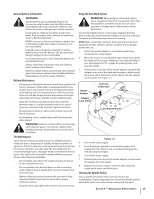
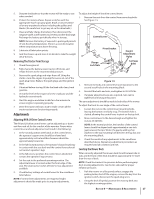
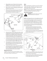
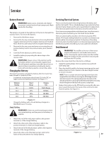
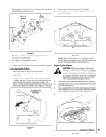
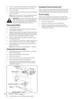
3. Measure blade-to-ground height at the front tip of the right blade. To obtain an accurate measure, align blades in parallel with mower centerline, (i.e. front to back). Brakes NOTE: The parking brakes normally do not need to be adjusted. 4. Measure blade-to-ground height at the front tip of the left To adjust either brake individually, loosen the jam nuts on the blade. Be sure to measure at the blade tip with the blades cable near the brake arm on the transaxle. Adjust the nuts so arranged in proper position. that the brake cable becomes shorter. 5. With a 3⁄4" wrench loosen the lower jam nut of the left side of the lift link. To adjust the side of the deck up or down turn the upper jam nut clockwise (to raise) or counter Repair: The mower is equipped with internal gear/pawl brakes and will not normally require maintenance. If they are not working properly, please contact your service center. clockwise (to lower) a few turns. See Figure 1-6. Adjusting the Gauge Wheels Outer Jam Nuts Front of Unit WARNING! Keep hands and feet away from the discharge opening of the cutting deck. Trailing Link Left Side Jam Nut Inner Jam Nuts Right Side Adjustable Lift Link Figure 1-6 6. Measure the blade-to-ground height at the right rear blade tip. Again be sure to measure at the blade tip at the rear of the right blade when aligned along the mower centerline. The blade-to-ground height at the rear of the blade tip should be approximately 1⁄4" higher than the front tip. This is referred to as blade pitch. The same height difference should be true for the left blade, measured front and back. 7. To change the pitch (front to rear), loosen the lower nuts on the rear Lift Links. With a few turns, adjust clockwise (to raise) or counter clockwise (to lower) the upper nuts of the rear Lift Links. Once the deck is adjusted, retighten lower nuts. 8. The final adjustment would be to set the Trailing Link by adjusting the jam nuts on the threaded link. Loosen the jam nuts and tighten the inner nut to achieve the correct length and belt tension. See Figure 1-6. 9. In many cases it will be necessary to adjust deck height using both eyebolt adjustments and pitch adjustment to achieve the correct blade-to-ground heights. If you remember that the front right blade tip adjustment is fixed and you level to that height, adjusting the decks will be simplified. Adjusting the Belt Tension To tighten or loosen the tension on the belt, tighten or loosen the jam nuts on the U-rod, see Figure 1-6, until a ten-pound pull with a spring scale deflects the belt about 1⁄2". NOTE: The deck gauge wheels are an anti-scalp feature of the deck and are not designed to support the weight of the cutting deck. The mower deck cutting height can be set using the tractor's deck lift pedal. The deck heights range from 1" to 4". The deck gauge wheel position should be approximately 1⁄4 to 1⁄2" above the ground when the deck is set in the desired height setting. Using the lift pedal, set the deck in the desired height setting, then check the gauge wheel distance from the ground below. If necessary, adjust as follows: 1. Visually check the distance between the front gauge wheels and the ground. If the gauge wheels are near or touching the ground, they should be raised. If more than 1⁄2" above the ground, they should be lowered. 2. Remove the lock nut securing one of the front gauge wheel shoulder screws to the deck. Remove the gauge wheel and hex screw. Refer to Figure 1-7. Lock Nut Deck Wheel Washer Hex Screw Wheel Spacer Figure 1-7 3. Insert the hex screw into the one of three index holes in the front gauge wheel bracket that will give the gauge wheel a 1⁄4" to 1⁄2" clearance with the ground. 4. Note the index hole of the just adjusted wheel, and adjust the other gauge wheels into the respective index holes of the other gauge wheel brackets on the deck. 28 Section 6- Maintenance & Adjustments
-
 1
1 -
2
-
3
-
4
-
5
-
6
-
7
-
8
-
9
-
10
-
11
-
12
-
13
-
14
-
15
-
16
-
17
-
18
-
19
-
20
-
21
-
22
-
 23
23 -
 24
24 -
 25
25 -
 26
26 -
 27
27 -
 28
28 -
 29
29 -
 30
30 -
 31
31 -
 32
32 -
 33
33 -
34
-
35
-
36
-
37
-
38
-
39
-
40
 |
 |
