Cub Cadet Z-Force 48 Z-Force 48 Operator's Manual - Page 9
Assembly & Set-Up - cut
 |
View all Cub Cadet Z-Force 48 manuals
Add to My Manuals
Save this manual to your list of manuals |
Page 9 highlights
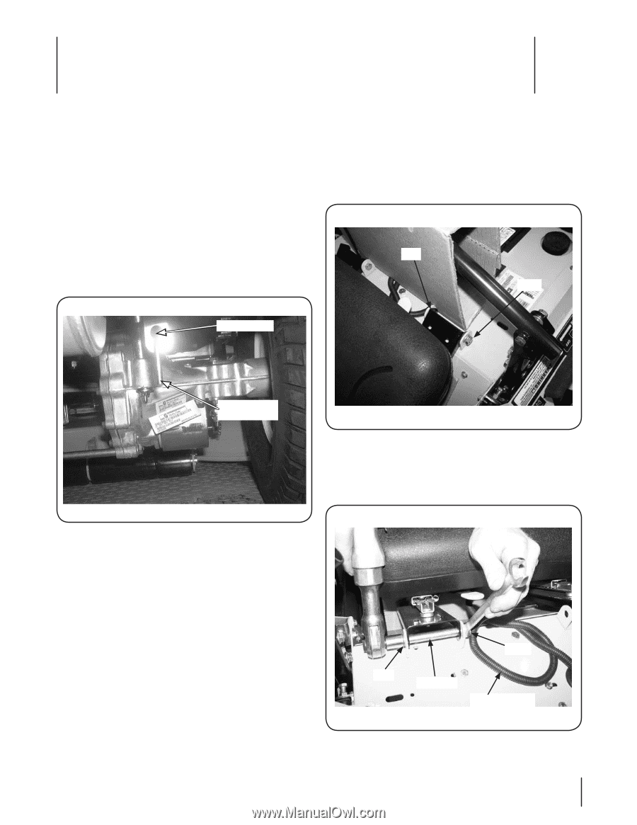
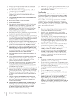
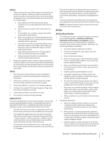
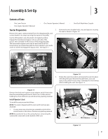
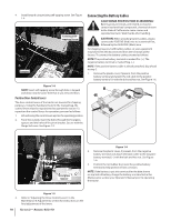
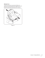
Assembly & Set-Up 3 Contents of Crate • One Lawn Tractor • One Engine Operator's Manual • One Tractor Operator's Manual • One Deck Wash Hose Coupler Tractor Preparation 2. Remove the two shoulder bolts, nuts and spacers securing the seat as shown in Figure 1-2. Remove the upper crating material from the shipping pallet, and cut any bands or tie straps securing the tractor to the pallet. Use the lift handle to raise the deck to its highest position. Engage the transmission bypass rods on each side of the tractor; then carefully roll the tractor off the shipping pallet. Nut The transmission bypass rods (one for each the RH and LH transmission) are located beneath the frame platform, just inside each rear wheel. Disengage the bypass rods. See Figure 1-1. Bolt Keyhole Slot Transmission Bypass Rods Figure 1-2 3. Rotate the seat into position and secure the seat into place with the previously removed shoulder bolts, nuts and spacers. Be careful not to crimp or damage the wire harness while installing the seat. See Figure 1-3. Figure 1-1 Remove the deck wash system nozzle adapter and oil drain tube from the manual bag and store for future use. Cut the wire tie holding the chute deflector up and discard any packing material. Install Operator's Seat To install the seat proceed as follows: NOTE: The seat is shipped with the seat switch and seat pan attached. 1. Cut any straps securing the seat assembly and the drive control levers to the tractor. Remove any packing material. NOTE: Be careful not to cut the wiring harness connecting the seat and the seat switch in the bottom of the seat. Bolt Nut Spacer Wire Harness Figure 1-3 9
-
 1
1 -
2
-
3
-
 4
4 -
 5
5 -
 6
6 -
 7
7 -
 8
8 -
 9
9 -
 10
10 -
 11
11 -
 12
12 -
 13
13 -
 14
14 -
15
-
16
-
17
-
18
-
19
-
20
-
21
-
22
-
23
-
24
-
25
-
26
-
27
-
28
-
29
-
30
-
31
-
32
-
33
-
34
-
35
-
36
-
37
-
38
-
39
-
40
 |
 |