D-Link 800 Quick Guide - Page 4
Identifying Components
 |
UPC - 790069282072
View all D-Link 800 manuals
Add to My Manuals
Save this manual to your list of manuals |
Page 4 highlights
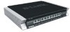
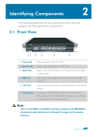
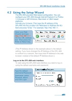
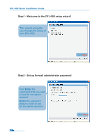
Identifying Components 2 The following illustrates the front panel of the DFL-800 and explains the front panel's key components: 2.1 Front View 12 3 4 5 6 1. Power LED 2. System LED 3. WAN Ports 4. DMZ Port 5. LAN Ports 6. Console Port Power indication of the DFL-800. System status indication of the DFL-800. These are for the connection of an Ethernet cable to a Cable or DSL modem. This is for the connection of an Ethernet cable to an DMZ network. These are for the connection of Ethernet cables to the internal network. Connects to RS-232 console cable that connects to PC. The console port is hidden behind a protection coverlid that can be opened by pulling down the lid. Note: None of the WAN1 and WAN2 interfaces support Auto MDI/MDI-X (Automatic cable detection for Straight-through and Crossover function. 02
-
 1
1 -
 2
2 -
 3
3 -
 4
4 -
 5
5 -
 6
6 -
 7
7 -
 8
8 -
 9
9 -
 10
10 -
11
-
12
-
13
-
14
-
15
-
16
-
17
-
18
-
19
-
20
 |
 |
