D-Link DES-1008PA Product Manual - Page 15
Front Panel, Rear Panel - power over ethernet switch
 |
UPC - 790069298172
View all D-Link DES-1008PA manuals
Add to My Manuals
Save this manual to your list of manuals |
Page 15 highlights
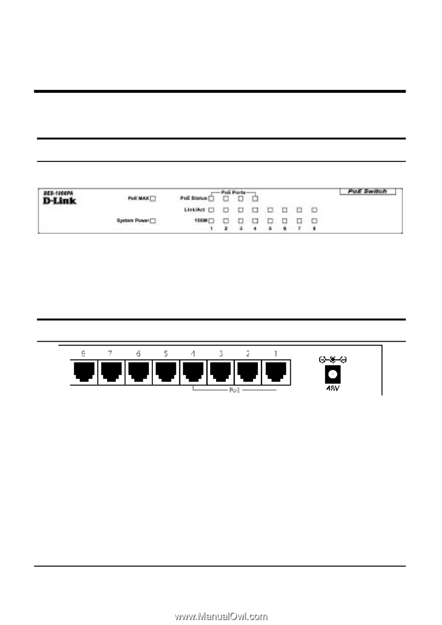
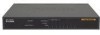
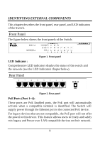
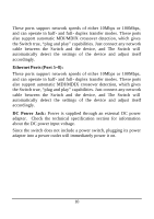
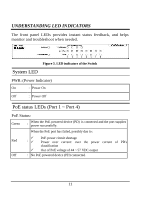
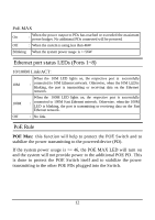
IDENTIFYING EXTERNAL COMPONENTS This chapter describes the front panel, rear panel, and LED indicators of the Switch. Front Panel The figure below shows the front panels of the Switch. Figure 1. Front panel LED Indicator : Comprehensive LED indicators display the status of the switch and the network (see the LED Indicators chapter below). Rear Panel Figure 2. Rear panel PoE Ports (Port 1~4): These ports are PoE Enabled ports, the PoE port will automatically activate when a compatible terminal is identified. The Switch will supply power through the Ethernet port to the connected PoE device. For legacy devices that are not compatible, the PoE port will not offer the power to this device. This feature allows users to freely and safely mix legacy and Power over LAN compatible devices on their network. 9
-
 1
1 -
2
-
3
-
4
-
5
-
6
-
7
-
8
-
9
-
 10
10 -
 11
11 -
 12
12 -
 13
13 -
 14
14 -
 15
15 -
 16
16 -
 17
17 -
 18
18 -
 19
19 -
 20
20 -
21
-
22
 |
 |