D-Link DES-5024 Product Manual - Page 12
Front Panel
 |
UPC - 790069216008
View all D-Link DES-5024 manuals
Add to My Manuals
Save this manual to your list of manuals |
Page 12 highlights
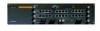
Fast Ethernet Switching System User's Guide Front Panel The DES-5024 is designed for management at a glance. The front of the DES-5024, displayed in Figure 1, has LEDs that give you essential information at a glance. The DES-5024 is a modular unit. The chassis has five slots. All the modules have LEDs. See Chapter 4, LEDs, for information on interpreting the LEDs. The slots are in the following order: CPU module is always on top. Slots one and two are full sized and cme with two 12-Port 10/100-TX Modules. Slots three and four are half sized and only slot 3 can accommodate feature modules. Slot 4 may not be used. All ports can be used for network connections. The RS-232 port is used for Out of Band Management. All LEDs are located on the front panel of the DES-5024. Their purpose is to allow you to monitor the operation and performance of the DES-5024 at a glance. Slot 1 CPU Module RS-232 Port Slot 2 4 4 Slot 3 Fiber Optic Ports Figure 1: DES-5024 Front Panel MDI-X Ports Slot 4 Introduction 4
-
 1
1 -
2
-
3
-
4
-
5
-
6
-
 7
7 -
 8
8 -
 9
9 -
 10
10 -
 11
11 -
 12
12 -
 13
13 -
 14
14 -
 15
15 -
 16
16 -
 17
17 -
18
-
19
-
20
-
21
-
22
-
23
-
24
-
25
-
26
-
27
-
28
-
29
-
30
-
31
-
32
-
33
-
34
-
35
-
36
-
37
-
38
-
39
-
40
-
41
-
42
-
43
-
44
-
45
-
46
-
47
-
48
-
49
-
50
-
51
-
52
-
53
-
54
-
55
-
56
-
57
-
58
-
59
-
60
-
61
-
62
-
63
-
64
-
65
-
66
-
67
-
68
-
69
-
70
-
71
-
72
-
73
-
74
-
75
-
76
-
77
-
78
-
79
-
80
-
81
-
82
-
83
-
84
-
85
-
86
-
87
-
88
-
89
-
90
-
91
-
92
-
93
 |
 |
