D-Link DFL-2560G Hardware Installation Guide - Page 5
Connecting Power and Turning On/Off, Connecting the Device to a Network
 |
UPC - 790069335440
View all D-Link DFL-2560G manuals
Add to My Manuals
Save this manual to your list of manuals |
Page 5 highlights
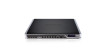
2. Use the screws provided with the equipment rack to mount the device in the rack. Connecting the Device to a Network This section provides basic information about physically connecting the DFL-2560 or DFL-2560G to a network. Follow the steps below to connect the firewall as shown in Figure 8. 1. Connect an RJ-45 cable from the port labeled 1 to the external router. The port No. 5 is pre-allocated to the WAN1 network segment. Figure 7. Installation Using a Standard-sized Equipment Rack Connecting Power and Turning On/Off The AC Power cord shipped with the device connects the device to earth ground when plugged an AC grounding-type power outlet. The device must be connected to earth ground during normal operation. 2. Connect an RJ-45 cable from the port labeled 1 to a switch in the DMZ1 network segment. 3. Connect an RJ-45 cable from the port labeled 7 to a switch in the LAN1 network segment. 4. Connect an RS-232 cable from the console port to a computer for CLI (Command Line Interface) management access. To connect power to the device, plug one Internet end of the AC power core into the AC power appliance inlet on the back panel of the device. WAN1 Plug the other end into an AC power source. DMZ LAN1 Console Note: D-Link recommends the use of a surge protector with your power connection. To power on the DFL-2560/2560G device, press the AC power switch on the rear panel to Server Fram the on position. To power off the device, press Users the power switch to the off position. Figure 8. Basic Cabling Example D-Link NetDefend Firewall 5
-
 1
1 -
 2
2 -
 3
3 -
 4
4 -
 5
5 -
 6
6 -
 7
7 -
 8
8 -
 9
9 -
 10
10 -
 11
11 -
12
-
13
-
14
-
15
-
16
-
17
-
18
-
19
-
20
-
21
-
22
-
23
-
24
-
25
-
26
-
27
-
28
-
29
-
30
-
31
-
32
-
33
-
34
-
35
-
36
-
37
-
38
-
39
-
40
-
41
-
42
-
43
-
44
 |
 |
