D-Link DGS-1024T Product Manual - Page 14
Power
 |
UPC - 790069242151
View all D-Link DGS-1024T manuals
Add to My Manuals
Save this manual to your list of manuals |
Page 14 highlights
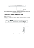
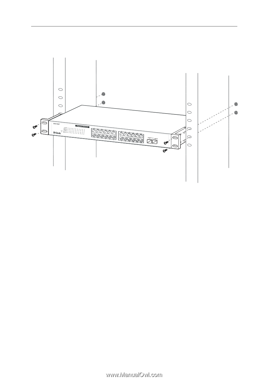
D-Link DGS-1024T Unmanaged Gigabit Ethernet Switch Mounting the Switch in a standard 19" rack. Power On Figure 2- 3. Installing Switch in a rack Plug one end of the AC power cord into the power connector of the Switch and the other end into the local power source outlet. After the Switch is powered on, the LED indicators will momentarily blink. This blinking of the LED indicators means the system is resetting. Power Failure As a precaution, in the event of a power failure, unplug the Switch. When power is resumed, plug the Switch back in. 14
-
 1
1 -
2
-
3
-
4
-
5
-
6
-
7
-
8
-
 9
9 -
 10
10 -
 11
11 -
 12
12 -
 13
13 -
 14
14 -
 15
15 -
 16
16 -
 17
17 -
 18
18 -
 19
19 -
20
-
21
-
22
-
23
-
24
-
25
-
26
 |
 |
D-Link DGS-1024T Unmanaged Gigabit Ethernet Switch
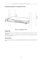
Mounting the Switch in a standard 19” rack.
Figure 2- 3. Installing Switch in a rack
Power On
Plug one end of the AC power cord into the power connector of the Switch and the other end into the local power
source outlet.
After the Switch is powered on, the LED indicators will momentarily blink. This blinking of the LED indicators
means the system is resetting.
Power Failure
As a precaution, in the event of a power failure, unplug the Switch. When power is resumed, plug the Switch
back in.
14