D-Link DGS-1024T Product Manual - Page 15
Connecting The Switch
 |
UPC - 790069242151
View all D-Link DGS-1024T manuals
Add to My Manuals
Save this manual to your list of manuals |
Page 15 highlights
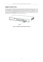
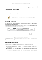
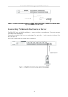
D-Link DGS-1024T Unmanaged Gigabit Ethernet Switch Connecting The Switch Switch To End Node Switch To Hub or Switch Connecting To Network Backbone or Server Section 3 NOTE: All twenty-four (24) high-performance NWay Ethernet ports can support both MDI-II and MDI-X connections. Switch To End Node End nodes include PCs, routers and other network devices outfitted with a 10, 100 or 1000 Mbps RJ-45 Ethernet/Fast Ethernet/Gigabit Ethernet ports. An end node can be connected to the Switch via a twisted-pair Category 3, 4, or 5 (or better) UTP/STP cable. The end node can be connected to any of the ports of the Switch. Figure 2- 4. Switch connected to an end node The Link/Act LEDs for each UTP port light green when the link is valid. The LED over the port label indicates a port speed of either 10/100 Mbps or 1000Mbps. A blinking LED on the bottom indicates packet activity on that port. Switch to Hub or Switch These connections can be accomplished in a number of ways using a Standard Ethernet patch cable. • A 10BASE-T hub or switch can be connected to the Switch via a twisted-pair Category 3, 4 or 5 UTP/STP cable. • A 100BASE-TX hub or switch can be connected to the Switch via a twisted -pair Category 5 UTP/STP cable. • A 1000BASE-TX switch can be connected to the Switch via a twisted -pair Category 5 (or better) UTP/STP cable. 15
-
 1
1 -
2
-
3
-
4
-
5
-
6
-
7
-
8
-
9
-
 10
10 -
 11
11 -
 12
12 -
 13
13 -
 14
14 -
 15
15 -
 16
16 -
 17
17 -
 18
18 -
 19
19 -
 20
20 -
21
-
22
-
23
-
24
-
25
-
26
 |
 |