D-Link DGS-1500-20 User Manual - Page 9
DGS-1500-20, Front Panel, Rear Panel
 |
View all D-Link DGS-1500-20 manuals
Add to My Manuals
Save this manual to your list of manuals |
Page 9 highlights
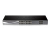
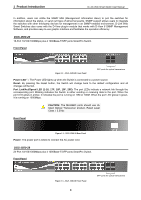
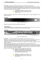
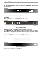
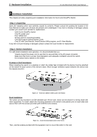
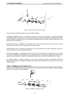
1 Product Introduction D-Link Web Smart Switch User Manual In addition, users can utilize the SNMP MIB (Management Information Base) to poll the switches for information about the status, or send out traps of abnormal events. SNMP support allows users to integrate the switches with other third-party devices for management in an SNMP-enabled environment. D-Link Web Smart Switches also come with the D-View plug-in module that works with D-View 6 SNMP Management Software, and provides easy-to-use graphic interface and facilitates the operation efficiency. DGS-1500-20 16-Port 10/100/1000Mbps plus 4 1000Base-T/SFP ports SmartPro Switch. Front Panel Figure 1.1 - DGS-1500-20 Front Panel SFP ports for optical transceivers Power LED : The Power LED lights up when the Switch is connected to a power source. Reset: By pressing the Reset button, the Switch will change back to the default configuration and all changes will be lost. Port Link/Act/Speed LED (1-16, 17F, 18F, 19F, 20F): The port LEDs indicate a network link through the corresponding port. Blinking indicates the Switch is either sending or receiving data to the port. When the port LED glows in amber, it indicates the port is running on 10M or 100M. When the port LED glows in green, it is running on 1000Mbps. CAUTION: The MiniGBIC ports should use UL listed Optical Transceiver product, Rated Laser Class I. 3.3Vdc Rear Panel Figure 1.2 - DGS-1500-20 Rear Panel Power: The power port is where to connect the AC power cord. DGS-1500-28 24-Port 10/100/1000Mbps plus 4 1000Base-T/SFP ports SmartPro Switch. Front Panel Figure 1.3 - DGS-1500-28 Front Panel 3 SFP ports for optical transceivers
-
 1
1 -
2
-
3
-
 4
4 -
 5
5 -
 6
6 -
 7
7 -
 8
8 -
 9
9 -
 10
10 -
 11
11 -
 12
12 -
 13
13 -
 14
14 -
15
-
16
-
17
-
18
-
19
-
20
-
21
-
22
-
23
-
24
-
25
-
26
-
27
-
28
-
29
-
30
-
31
-
32
-
33
-
34
-
35
-
36
-
37
-
38
-
39
-
40
-
41
-
42
-
43
-
44
-
45
-
46
-
47
-
48
-
49
-
50
-
51
-
52
-
53
-
54
-
55
-
56
-
57
-
58
-
59
-
60
-
61
-
62
-
63
-
64
-
65
-
66
-
67
-
68
-
69
-
70
-
71
-
72
-
73
-
74
-
75
-
76
-
77
-
78
-
79
-
80
-
81
-
82
-
83
-
84
-
85
-
86
-
87
-
88
-
89
-
90
-
91
-
92
-
93
-
94
-
95
-
96
-
97
-
98
-
99
-
100
-
101
-
102
-
103
-
104
-
105
-
106
-
107
-
108
-
109
-
110
-
111
-
112
-
113
-
114
-
115
 |
 |
