D-Link DGS-1520 Quick Install Guide - Page 10
Color, Status, Description, PoE Switches Only
 |
View all D-Link DGS-1520 manuals
Add to My Manuals
Save this manual to your list of manuals |
Page 10 highlights
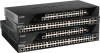
DGS-1520 Series Gigabit Ethernet Smart Managed Switch Hardware Installation Guide LED Fan Error Link/Act Mode (PoE Switches Only) PoE Mode (PoE Switches Only) Stack ID (7-segment LED) Color Green Red Green Green Green Status On (Solid) On (Solid) On (Solid) Off On (Solid) Off On (Solid) 1 to 8 On (Solid) H On (Solid) h On (Solid) e On (Solid) G Description Normal operation (diagnostics test passed) Fan off (due to fan runtime failure) Link/Act/Speed mode selected (via Mode button) PoE mode selected (via Mode button) PoE mode selected (via Mode button) Link/Act/Speed mode selected (via Mode button) The stacking ID number of the switch in the stack The switch is the master switch in the stack The switch is the backup master switch in the stack There was an error in the system's self-test The Safeguard engine entered the exhausted mode The front panel LED indicators (per RJ45 port) are described in the following table: LED Color Status Description Link/Act (1G, 10/100M) (top of each port) Green Amber On (Solid) On (Blinking) On (Solid) Active connection at 1 Gbps through the port Data transmitted and received through the port Active connection at 10/100 Mbps through the port On (Blinking) Data transmitted and received through the port Off Off Inactive connection or no link present Link/Act (2.5G, 100M/1G) (PoE Switches Only) (top of each port) Green Amber On (Solid) On (Blinking) On (Solid) On (Blinking) Active connection at 2.5 Gbps through the port Data transmitted and received through the port Active connection at 100 Mbps or 1 Gbps through port Data transmitted and received through the port Off Off Inactive connection or no link present Link/Act (10G, 1G) (top of each port) Green Amber On (Solid) On (Blinking) On (Solid) Active connection at 10 Gbps through the port Data transmitted and received through the port Active connection at 1 Gbps through the port On (Blinking) Data transmitted and received through the port Off Off Inactive connection or no link present PoE OK/Fail (PoE Switches Only) (top of each port) Green Amber Off On (Solid) On (Solid) Off Power being supplied to PD through the port An error condition is occurring No power being supplied through the port The front panel LED indicators (per SFP+ port) are described in the following table: LED Color Status Description Link/Act (top of each port) Green On (Solid) On (Blinking) Active connection at 10 Gbps through the port Data transmitted and received through the port Amber On (Solid) Active connection at 1 Gbps through the port On (Blinking) Data transmitted and received through the port Off Off Link down or no link 5
-
 1
1 -
2
-
3
-
4
-
 5
5 -
 6
6 -
 7
7 -
 8
8 -
 9
9 -
 10
10 -
 11
11 -
 12
12 -
 13
13 -
 14
14 -
 15
15 -
16
-
17
-
18
-
19
-
20
-
21
-
22
-
23
-
24
-
25
-
26
-
27
-
28
-
29
-
30
-
31
-
32
-
33
-
34
-
35
-
36
-
37
-
38
-
39
-
40
-
41
-
42
-
43
-
44
-
45
-
46
-
47
-
48
-
49
-
50
-
51
-
52
-
53
-
54
-
55
-
56
-
57
-
58
-
59
-
60
-
61
-
62
 |
 |
