D-Link DGS-3630-28TC Hardware Installation Guide - Page 21
Component, Description, Power Cord Retainer Hole
 |
View all D-Link DGS-3630-28TC manuals
Add to My Manuals
Save this manual to your list of manuals |
Page 21 highlights
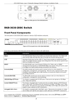
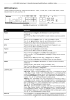
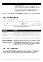
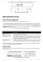
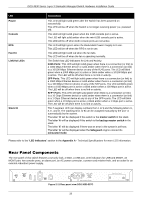
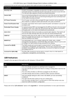
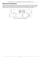
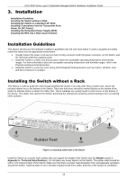
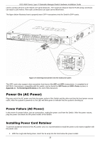
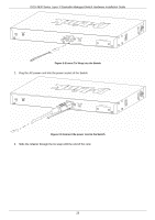
DGS-3630 Series Layer 3 Stackable Managed Switch Hardware Installation Guide Components that can be found on the rear panel of this switch are listed in the table below. Component Description Security Lock Switch GND AC Power Connector Power Cord Retainer Hole Redundant Power Supply Alarm Port USB Port MGMT Port Console Port (RJ45) Console Port (Mini-USB) Provide a Kensington-compatible security lock to be able to connect to a secure immovable device. Insert the lock into the notch and turn the key to secure the lock. The lock-and-cable apparatus should be purchased separately. Use an electrical grounding wire and connect one end of the wire to the Switch GND and the other end of the wire to an electrical grounding point most commonly found on the Switch mounting rack itself. The AC power cord with a three-pronged AC power connector can be plugged into this receptacle to supply the Switch with 100-240 VAC power at 50-60 Hz. The power cord retainer hole is used to insert the power cord retainer to secure the AC power cord. An optional external RPS can be plugged into the RPS port found on the rear panel of switches in this series. When the internal power fails, this optional external RPS will supply power to the Switch immediately and automatically. The RJ45 (8 pins) Alarm port provides an external alarm detection. The Switch will send out the traps and logs when two of the pins are shorted among the pair. Inserting a flash drive into the USB 2.0 Type-A port provides an additional storage space for portable firmware images and configuration files that can be copied to and from the NVRAM of the Switch. The RJ45 MGMT port is an IP-based, OOB port for Telnet, web, or SNMP management that operates at 10/100/1000 Mbps wire-speed. This port can be used to configure the Switch without being connected to the network. The RJ45 console port can be used to connect to the CLI of the Switch for configuration, management, and monitoring. This port uses a special console cable (included in this package) with a DB9 interface to connect the Switch to the serial port (COM) of the PC. The Mini-USB console port can be used to connect to the CLI of the Switch for configuration, management, and monitoring. LED Indicators Located on the rear panel of this switch are LED indicators: USB and MGMT. LED USB MGMT Description This LED will light solid green if a USB flash drive is plugged in. This LED will blink green when the Switch is reading or writing data to and from the USB drive. This LED will be off when no USB drive is plugged into the USB port. This LED will light solid red when a USB drive failure has been detected. This LED will light solid green after a link to the MGMT port was successfully established. This LED will blink when activity on this port is taking place. This LED will be off when there is no link present or when this interface was shut down from within the Switch's configuration. Please refer to the "LED Indicators" section in the Appendix A - Technical Specifications for more LED information. 21
-
 1
1 -
2
-
3
-
4
-
5
-
6
-
7
-
8
-
9
-
10
-
11
-
12
-
13
-
14
-
15
-
 16
16 -
 17
17 -
 18
18 -
 19
19 -
 20
20 -
 21
21 -
 22
22 -
 23
23 -
 24
24 -
 25
25 -
 26
26 -
27
-
28
-
29
-
30
-
31
-
32
-
33
-
34
-
35
-
36
-
37
-
38
-
39
-
40
-
41
-
42
-
43
-
44
-
45
-
46
-
47
-
48
-
49
-
50
-
51
-
52
-
53
-
54
-
55
-
56
-
57
-
58
-
59
-
60
-
61
-
62
-
63
-
64
-
65
-
66
-
67
-
68
-
69
-
70
-
71
-
72
 |
 |