D-Link DGS-3630-28TC Hardware Installation Guide - Page 29
Installing the RPS into a Rack-mount Chassis, DPS-800 Rack-mount Chassis
 |
View all D-Link DGS-3630-28TC manuals
Add to My Manuals
Save this manual to your list of manuals |
Page 29 highlights
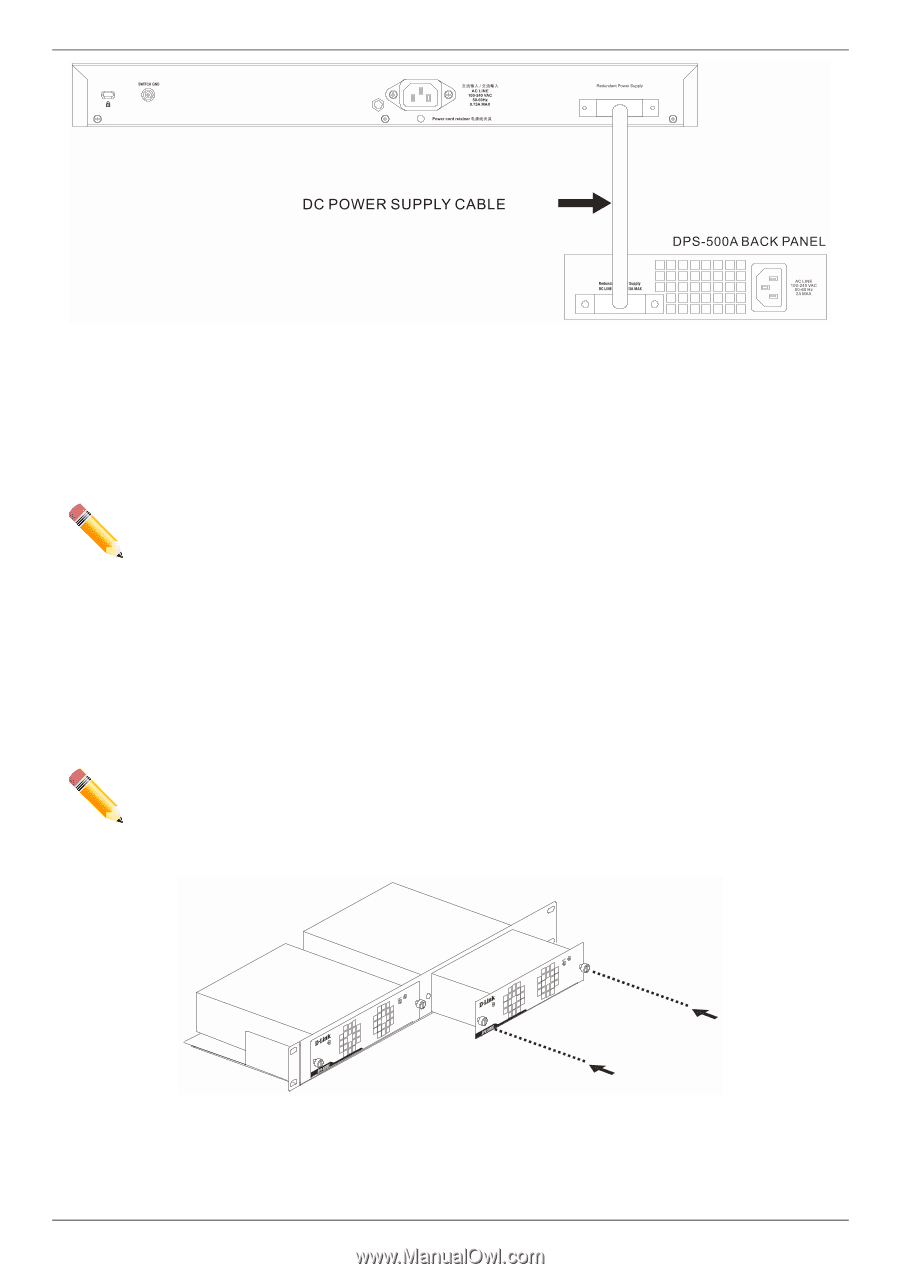
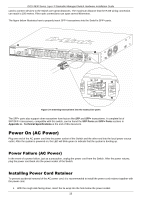
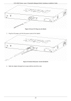
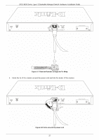
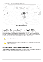
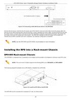
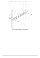
DGS-3630 Series Layer 3 Stackable Managed Switch Hardware Installation Guide Figure 3-10 Connecting a DGS-3630 Series Switch to the DPS-500A Remove the AC power cord from the AC power port of the Switch. Insert one end of the 14-pin DC power cable into the port on the switch and the other end into the RPS. Using a standard AC power cable, connect the RPS to the main AC power source. A green LED on the front of the RPS will glow to indicate a successful connection. Reconnect the AC power cord to the AC power port of the Switch. The RPS LED indicator on the front panel of the Switch will indicate that an RPS is present and now in operation. No software configuration is required. NOTE: See the DPS-500A and DPS-500DC documentation for more information. Installing the RPS into a Rack-mount Chassis DPS-800 Rack-mount Chassis The DPS-800 is a standard-size (1 standard unit in height) rack-mountable unit designed to hold up to two RPS units. NOTE: This rack-mount chassis supports the following RPS units: DPS-500A and DPS-500DC. The following diagram illustrates how a DPS-500A is installed into a DPS-800. Figure 3-11 Install the DPS-500A in the DPS-800 The DPS-800 can be mounted into a standard 19" rack, as shown below. 29
-
 1
1 -
2
-
3
-
4
-
5
-
6
-
7
-
8
-
9
-
10
-
11
-
12
-
13
-
14
-
15
-
16
-
17
-
18
-
19
-
20
-
21
-
22
-
23
-
 24
24 -
 25
25 -
 26
26 -
 27
27 -
 28
28 -
 29
29 -
 30
30 -
 31
31 -
 32
32 -
 33
33 -
 34
34 -
35
-
36
-
37
-
38
-
39
-
40
-
41
-
42
-
43
-
44
-
45
-
46
-
47
-
48
-
49
-
50
-
51
-
52
-
53
-
54
-
55
-
56
-
57
-
58
-
59
-
60
-
61
-
62
-
63
-
64
-
65
-
66
-
67
-
68
-
69
-
70
-
71
-
72
 |
 |