D-Link DGS-3630-28TC Hardware Installation Guide - Page 31
Switch Connections, Switch to an End Node, Switch to Another Switch
 |
View all D-Link DGS-3630-28TC manuals
Add to My Manuals
Save this manual to your list of manuals |
Page 31 highlights
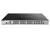
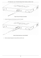
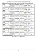
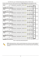
DGS-3630 Series Layer 3 Stackable Managed Switch Hardware Installation Guide 4. Switch Connections Switch to an End Node Switch to Another Switch Switch Stacking Switch to a Server Switch to an End Node An end node is a generic name for edge networking devices that will be connected to this switch. Typical examples of end nodes are Personal Computers (PCs), Notebooks, Access Points, Print Servers, VoIP Phones and more. Each end node should be fitted with a 100/1000/10000 Mbps RJ45 networking port. Normally, end nodes will connect to this switch by using a standard twisted-pair UTP/STP network cable. When a successful connection is established, the corresponding port light will illuminate and blink to indicate that network activity is taking place on that port. The diagram below displays a typical end node connected to the Switch. Figure 4-1 Connecting the Switch to an End Node Switch to Another Switch The Switch can be used to connect to any other switch or hub in the network. This network topology is used when the Switch does not have enough ports to cater for all the end nodes in the network. There is a great deal of flexibility on how connections are made using the appropriate cabling. Connect a 10BASE-T switch port to the Switch using a twisted-pair Category 3, 4, or 5 UTP/STP cable. Connect a 100BASE-TX switch port to the Switch via a twisted-pair Category 5 UTP/STP cable. Connect a 1000BASE-T switch port to the Switch via a twisted pair Category 5e UTP/STP cable. Connect a switch supporting an optical fiber uplink to the Switch's SFP/SFP+ ports via fiber optical cabling. Figure 4-2 Connecting the Switch to another switch/hub 31
-
 1
1 -
2
-
3
-
4
-
5
-
6
-
7
-
8
-
9
-
10
-
11
-
12
-
13
-
14
-
15
-
16
-
17
-
18
-
19
-
20
-
21
-
22
-
23
-
24
-
25
-
 26
26 -
 27
27 -
 28
28 -
 29
29 -
 30
30 -
 31
31 -
 32
32 -
 33
33 -
 34
34 -
 35
35 -
 36
36 -
37
-
38
-
39
-
40
-
41
-
42
-
43
-
44
-
45
-
46
-
47
-
48
-
49
-
50
-
51
-
52
-
53
-
54
-
55
-
56
-
57
-
58
-
59
-
60
-
61
-
62
-
63
-
64
-
65
-
66
-
67
-
68
-
69
-
70
-
71
-
72
 |
 |