D-Link DI-524 Quick Installation Guide - Page 3
Restart Your Computer - install
 |
UPC - 790069282546
View all D-Link DI-524 manuals
Add to My Manuals
Save this manual to your list of manuals |
Page 3 highlights
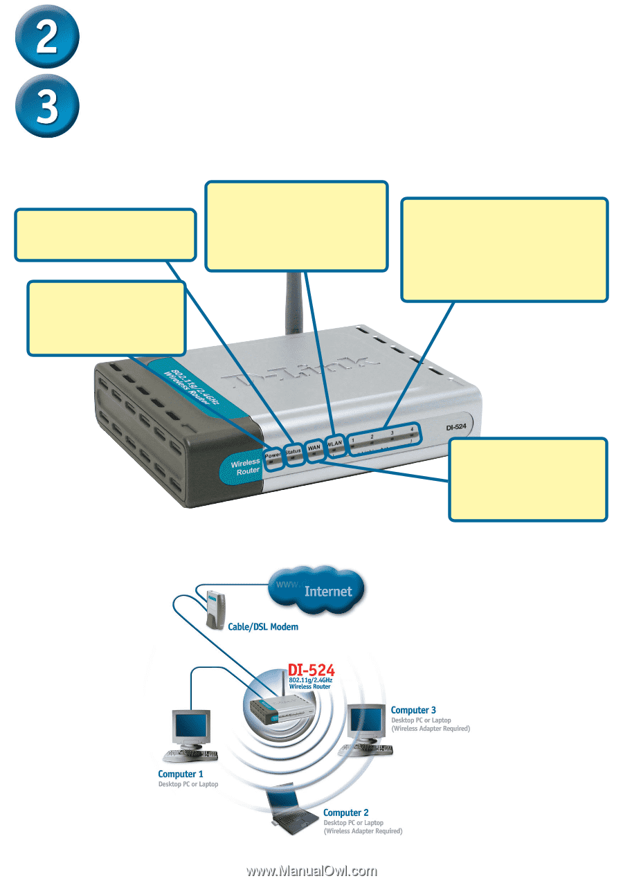
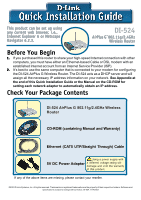
Restart Your Computer Connecting Additional Computers To The DI-524 Using additional Ethernet (CAT5 UTP) cables, connect your Ethernet-equipped computers to the remaining Ethernet LAN ports on the back panel of the DI-524. Status LED - a blinking light indicates that the DI-524 is functioning properly. WLAN LED - a solid light indicates that the wireless segment is ready. This LED blinks during wireless data transmission. Power LED - a solid light indicates a proper connection to the power supply. LOCAL NETWORK LEDs - a solid light on the port indicates a connection to an Ethernet enabled computer on ports 1-4. This LED blinks during data transmission. WAN LED - a solid light indicates connection on the WAN port. This LED blinks during data transmission. When you have completed the steps in this Quick Installation Guide, your connected network should look similar to this: 3
-
 1
1 -
 2
2 -
 3
3 -
 4
4 -
 5
5 -
 6
6 -
 7
7 -
 8
8 -
 9
9 -
10
-
11
-
12
 |
 |