D-Link DSN-2100-10 User's Manual for DSN-2100-10 Valid for firmware - Page 16
Key Lock and Latches
 |
UPC - 790069310638
View all D-Link DSN-2100-10 manuals
Add to My Manuals
Save this manual to your list of manuals |
Page 16 highlights
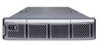
2.1.1 LEDs Figure 2-1 reveals several LEDs that provide useful information about the state of the xStack Storage Array. The Power LED illuminates when the system is powered. The bicolor Boot and Fault LED will remain clear during bootup and then green if booting is successful. If the boot process is unsuccessful, or a system fault occurs, then it will turn red. Each of the fifteen drive bays has two LEDs associated with it, a bicolor drive activity and fault LED and a drive power LED. Table 2-1 describes the front panel LEDs and their functions. Table 2-1 Front Panel LED indicators on the DSN-3000 series enclosure LED Color Meaning Power Green ON Power is applied to the system Boot and Fault Green ON Red ON Successful boot. No errors encountered. Remains clear during boot process. If red after boot process completed, then an error has been encountered. Please see management GUI for more information. Drive Power Blue ON Drive is powered and operational. Drive Activity and Fault Green Blinking Red ON Data being transmitted or received from corresponding SATA drive. Drive has experienced a fault and is offline 2.1.2 Key Lock and Latches Figure 2-1 shows the xStack Storage Array's front bezel with key lock and one latch. This bezel can be locked in place to protect the system from unauthorized drive access and removal. Bezel Removal: Simply press inwards (as the arrow reveal) on the left latch shown in Figure 2-1 and pull the left side outwards. The bezel will come off easily providing access to the drive bays behind it. If the key lock is in the locked position, then the latch cannot be pressed inwards. Bezel Installation: Align the bezel in front of the chassis with the bezel slightly to the left. Carefully insert the catch found on the right side of the bezel under the receptacle found on the right-front of the chassis and push the left side of the bezel to the right and forward until the latch locks. The latch is spring-loaded and will lock into place. If you wish, you can use the key lock to prevent drive access by turning it to the locked position. 16 Chapter 2 Identifying Hardware Components
-
 1
1 -
2
-
3
-
4
-
5
-
6
-
7
-
8
-
9
-
10
-
 11
11 -
 12
12 -
 13
13 -
 14
14 -
 15
15 -
 16
16 -
 17
17 -
 18
18 -
 19
19 -
 20
20 -
 21
21 -
22
-
23
-
24
-
25
-
26
-
27
-
28
-
29
-
30
-
31
-
32
-
33
-
34
-
35
-
36
-
37
-
38
-
39
-
40
-
41
-
42
-
43
-
44
-
45
-
46
-
47
-
48
-
49
-
50
-
51
-
52
-
53
-
54
-
55
-
56
-
57
-
58
-
59
-
60
-
61
-
62
-
63
-
64
-
65
-
66
-
67
-
68
-
69
-
70
-
71
-
72
-
73
-
74
-
75
-
76
-
77
-
78
-
79
-
80
-
81
-
82
-
83
-
84
-
85
-
86
-
87
-
88
-
89
-
90
-
91
-
92
-
93
-
94
-
95
-
96
-
97
-
98
-
99
-
100
-
101
-
102
-
103
-
104
-
105
-
106
-
107
-
108
-
109
-
110
-
111
-
112
-
113
-
114
-
115
-
116
-
117
-
118
-
119
-
120
-
121
-
122
-
123
-
124
-
125
-
126
-
127
-
128
-
129
-
130
-
131
-
132
-
133
-
134
-
135
-
136
-
137
-
138
-
139
-
140
-
141
-
142
-
143
-
144
-
145
-
146
-
147
-
148
-
149
-
150
-
151
-
152
-
153
-
154
-
155
-
156
-
157
-
158
-
159
-
160
-
161
-
162
-
163
-
164
-
165
-
166
 |
 |
