D-Link DSN-5210-10 Hardware Reference Guide for DSN-5000-10 - Page 20
Rear Panel Components
 |
UPC - 790069323980
View all D-Link DSN-5210-10 manuals
Add to My Manuals
Save this manual to your list of manuals |
Page 20 highlights
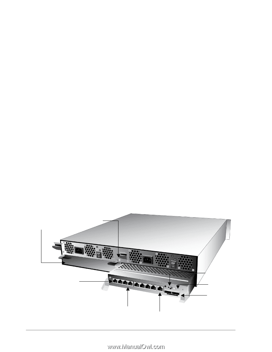
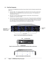
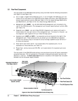
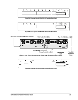
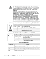
2.2 Rear Panel Components The rear panel of the DSN-5000 series primary array controller has the following components (see Figure 2-4 and Figure 2-5): Four or Eight 1-Gigabit RJ-45 iSCSI data ports, or one 10-Gigabit XFP iSCSI data port are located on the rear panel of the DSN-5000 series chassis controllers. Each iSCSI data port has port speed and port activity LEDs (see Table 2-4 for the xStack Storage DSN-5110-10 and DSN-5210-10, and Table 2-5 for the xStack Storage DSN-5410-10). Management port (MGMT) - one 10/100/1000 RJ-45 management port is located to the right of the iSCSI data ports. The management port has port speed and port activity LEDs (see Table 2-4) Diagnostic port (DIAG) - one 115.2 Kbps RS-232-C diagnostic port (stereo mini-jack) is located above the top-right corner of the management port. To connect to this port, use the diagnostic cable supplied with your xStack Storage system. Expansion ports (EXP0 and EXP1) - two expansion ports are located to the right of the management port. These connectors let you attach up to six DSN-5000-10 expansion arrays to the primary array to increase the array's storage capabilities (see Section 4.7 for more information). Reset switch and restart switch - are located above the expansion ports. For an explanation of these switches, see Table 2-6. Ready/fault, battery status and A/B LEDs - are located above the expansion ports (see Table 2-7). The rear panel of the DSN-5000 series primary array enclosure has two AC power receptacles and power switches. For an explanation of the power receptacles and power switches, see Sections 3.7 and 3.8. The Mute Audio Alarm button is located on the module that is located between the two AC power supply modules. Redundant Controller or Filler Plate in Slot #1 Mute Audio Alarm Button Four or eight 1-Gigabit iSCSI RJ-45 Ports Primary Controller in Slot #0 One Management Port Figure 2-4. Rear View of the DSN-5210-10 series Primary Array 12 Chapter 2 DSN-5000 Series Primary Array Layout Rear Panel Switches Rear Panel Status LEDs Two SAS Expansion Ports
-
 1
1 -
2
-
3
-
4
-
5
-
6
-
7
-
8
-
9
-
10
-
11
-
12
-
13
-
14
-
 15
15 -
 16
16 -
 17
17 -
 18
18 -
 19
19 -
 20
20 -
 21
21 -
 22
22 -
 23
23 -
 24
24 -
 25
25 -
26
-
27
-
28
-
29
-
30
-
31
-
32
-
33
-
34
-
35
-
36
-
37
-
38
-
39
-
40
-
41
-
42
-
43
-
44
-
45
-
46
-
47
-
48
-
49
-
50
-
51
-
52
 |
 |