D-Link DSN-5210-10 Hardware Reference Guide for DSN-5000-10 - Page 21
Close-up View of DSN-5210-10 Controller Rear Panel
 |
UPC - 790069323980
View all D-Link DSN-5210-10 manuals
Add to My Manuals
Save this manual to your list of manuals |
Page 21 highlights
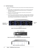
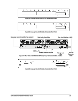
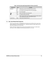
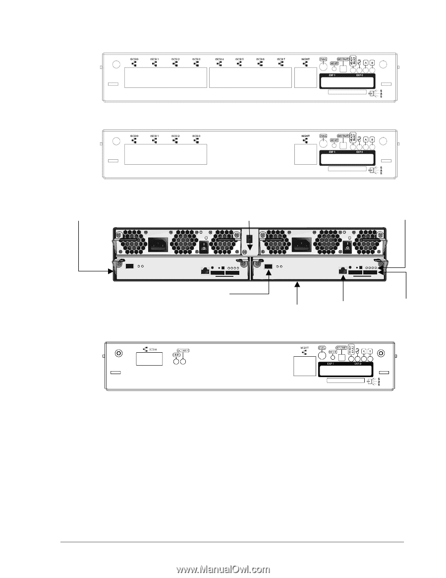
Figure 2-5. Close-up View of DSN-5210-10 Controller Rear Panel Figure 2-6. Close-up View of DSN-5210-10 Controller Rear Panel Redundant Controller or Filler Plate in Slot #1 Mute Audio Alarm Button Rear Panel Switches & LED's 10G Data Port Primary Controller in Slot #0 Management Port Figure 2-7. Rear View of the DSN-5410-10 Primary Array with two controllers installed Two SAS Expansion Ports Figure 2-8. Close-up View of DSN-5410-10 Controller Rear Panel DSN-5000 series Hardware Reference Guide 13
-
 1
1 -
2
-
3
-
4
-
5
-
6
-
7
-
8
-
9
-
10
-
11
-
12
-
13
-
14
-
15
-
 16
16 -
 17
17 -
 18
18 -
 19
19 -
 20
20 -
 21
21 -
 22
22 -
 23
23 -
 24
24 -
 25
25 -
 26
26 -
27
-
28
-
29
-
30
-
31
-
32
-
33
-
34
-
35
-
36
-
37
-
38
-
39
-
40
-
41
-
42
-
43
-
44
-
45
-
46
-
47
-
48
-
49
-
50
-
51
-
52
 |
 |
DSN-5000 series Hardware Reference Guide
13
Figure 2-5. Close-up View of DSN-5210-10 Controller Rear Panel
Figure 2-6. Close-up View of DSN-5210-10 Controller Rear Panel
Figure 2-7. Rear View of the DSN-5410-10 Primary Array with two controllers installed
Figure 2-8. Close-up View of DSN-5410-10 Controller Rear Panel
10G Data Port
Management
Port
Two SAS
Expansion
Ports
Redundant Controller or Filler Plate in Slot #1
Rear Panel Switches & LED’s
Primary Controller in Slot #0
Mute Audio Alarm Button