D-Link DSN-5210-10 Hardware Reference Guide for DSN-5000-10 - Page 29
xStack Storage DSN-5110-10 & 5210-10 Data Ports, xStack Storage DSN-5410-10 Data Port,
 |
UPC - 790069323980
View all D-Link DSN-5210-10 manuals
Add to My Manuals
Save this manual to your list of manuals |
Page 29 highlights
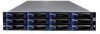
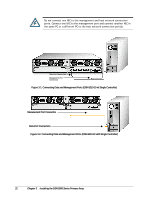
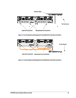
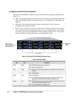
3.5.1 xStack Storage DSN-5110-10 & 5210-10 Data Ports The DSN-5110-10 & 5210-10 primary arrays have four or eight 1-Gigabit RJ-45 data ports labeled iSCSI 0 through iSCSI 7 (see Figure 2-4 and Figure 2-5). These ports connect to your SAN using either a straight-through or cross-over RJ-45 Ethernet cable (the DSN-5110-10 & 5210-10 primary arrays auto-sense the network link speed and type of cable used). One cable is needed for each RJ-45 data port. 1. Attach one end of an Ethernet cable to the data port labeled iSCSI 0 on the DSN-5110-10 or 5210-10 primary array back panel (see Figure 2-5 and Figure 3-1). Connect the other end of the cable to your SAN or host system. 2. To connect additional host network connection ports to your SAN, repeat step 1 using another Ethernet cable and the next available DSN-5110-10 or DSN-5210-10 primary array port in sequence (port iSCSI 1, then port iSCSI 2, and so on). 3.5.2 xStack Storage DSN-5410-10 Data Port The DSN-5410-10 primary array has one 10 Gigabit XFP iSCSI data port labeled iSCSI 0 (see Figure 2-7 and Figure 2-8). This port connects to an XFP module for the appropriate 10 gigabit network (for example, LR, SR, or CX4). 1. Connect one end of a single mode or multimode XFP optical cable to the DSN-5410-10 storage system optical host network connection port (see Figure 2-5 and Figure 3-2). 2. Connect the other end of the cable to your SAN or host system. 3.6 Connecting to the Management Port Connecting a PC to the management port lets you configure and manage the DSN-5000 series primary array. This connection is made using a PC with an installed NIC and either a crossover cable (if connecting directly to a 10/100 management port) or a straight-through cable (if connecting to a Gigabit Ethernet management port, or using a hub or switch). To receive email alerts from the DSN-5000 series primary array, be sure the management port can communicate via Ethernet with your mail server. 1. Connect either end of an Ethernet cable to a NIC installed in a PC. 2. Connect the other end of the cable into the DSN-5000 series primary array MGMT port (see Figure 2-5 , Figure 3-1, Figure 3-2, Figure 3-3 and Figure 3-4). DSN-5000 series Hardware Reference Guide 21
-
 1
1 -
2
-
3
-
4
-
5
-
6
-
7
-
8
-
9
-
10
-
11
-
12
-
13
-
14
-
15
-
16
-
17
-
18
-
19
-
20
-
21
-
22
-
23
-
 24
24 -
 25
25 -
 26
26 -
 27
27 -
 28
28 -
 29
29 -
 30
30 -
 31
31 -
 32
32 -
 33
33 -
 34
34 -
35
-
36
-
37
-
38
-
39
-
40
-
41
-
42
-
43
-
44
-
45
-
46
-
47
-
48
-
49
-
50
-
51
-
52
 |
 |