D-Link DSS-100E-9P Quick Install Guide 2 - Page 3
Before You Begin, Package Contents, Hardware Overview - d link
 |
View all D-Link DSS-100E-9P manuals
Add to My Manuals
Save this manual to your list of manuals |
Page 3 highlights
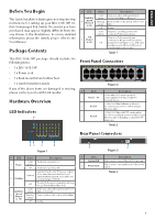
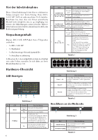
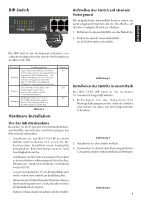
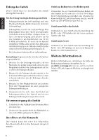
ENGLISH Before You Begin This Quick Installation Guide gives you step-by-step instructions for setting up your DSS-100E-18P 18Port Unmanaged PoE Switch. The model you have purchased may appear slightly different from the one shown in the illustrations. For more detailed information about the switch, please refer to the User Manual. Package Contents This DSS-100E-18P package should include the following items: • 1 x DSS-100E-18P 5 15 • 1 x Power cord 6 26 7 37 8 48 • 1 x Rack mount kit and rubber feet • 1 x Quick Installation Guide If any of the above items are damaged or missing, please contact your local D-Link reseller. Hardware Overview LED Indicators 4 5 15 6 26 7 37 8 48 # LED Link/Act/ 4 Speed (Ports 17 to 18) PoE 5 (Ports 1 to 16) Status Solid green Blinking green Off Solid amber Off Description There is an active link negotiated at 10/100/1000 Mbps on this port. There is traffic on the port at 10/100/1000 Mbps. No link The port is providing power to the connected PoE-powered device. There is no PoE-powered device connected to this port or PoE-powered device insert but failure occurs. (PSE can't provide power to PD due to PD error or power budget is not enough.) Table 1 Front Panel Connectors 9 10 11 12 13 14 15 16 17 18 1000 Link / Act Figure 2 # Item Description 10/100 Mbps PoE-capable ports for 1 Ports 1 ~16 connecting Ethernet devices and PoE- powered devices. 10/100/1000 Mbps Ethernet uplink port 2 Port 17 for connecting to another switch using an Ethernet cable. 10/100/1000 Mbps GbE/SFP combo uplink 3 Port 18 port for connecting to another switch using an Ethernet cable or installing a compatible SFP transceiver. 9 10 11 12 13 14 15 16 Table 2 Rear Panel Connectors 21 3 5 Figure 1 # LED 1 Power 2 PoE Max Link/Act/ 3 Speed (Ports 1 to 16) Status Solid green Off Solid red Off Solid amber Blinking amber Off Description The device is powered on. The device is powered off. Indicates that the total PoE power output of the switch has exceeded the Guard Band threshold of 223 W, but is still below the total budget of 230 W. The total PoE power consumption is below the 223 W Guard Band threshold. There is an active link negotiated at 10/100 Mbps on this port. There is traffic on the port at 10/100 Mbps. No link 1 2 Figure 3 # Item Description 1 Switch GND This is used to connect the switch to ground. 2 Power Input This is used to connect the power cable to the switch. Table 3 1
-
 1
1 -
 2
2 -
 3
3 -
 4
4 -
 5
5 -
 6
6 -
 7
7 -
 8
8 -
 9
9 -
10
-
11
-
12
-
13
-
14
-
15
-
16
-
17
-
18
-
19
-
20
 |
 |
