D-Link DSS-100E-9P Quick Install Guide 2 - Page 5
Additional Information
 |
View all D-Link DSS-100E-9P manuals
Add to My Manuals
Save this manual to your list of manuals |
Page 5 highlights
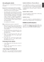
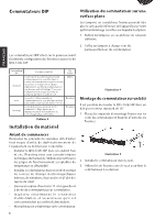
ENGLISH Grounding the Switch This step must be completed before powering on the switch. Required tools and equipment for grounding • Grounding screw (included) and one M4x6 (metric) pan-head screw (not included). • Grounding cable (not included). The grounding cable should be sized according to local and national installation requirements. Depending on the power supply and system, a 12 to 6 AWG copper conductor is required for installation. Commercially available 6 AWG wire is recommended. The length of the cable depends on the proximity of the switch to proper grounding facilities. • A screwdriver (not included). Note: Verify that the system is powered off. 1. Remove the grounding screw from the back of the device and place the #8 terminal lug ring of the grounding cable on top of the grounding screw opening. 2. Insert the grounding screw back into the screw opening and use a screwdriver to tighten the grounding screw. 3. Attach the terminal lug ring at the other end of the grounding cable to an appropriate grounding source. 4. Verify that the connection between the grounding connector on the switch and the grounding source is secure. Powering On the Switch 1. Connect the power cord to the power connector on the switch. 2. Plug the other end of the power cord into a nearby power socket. Switch to End Node or Powered Device Use a standard Ethernet cable to connect the switch to PCs with an 10/100/1000 Mbps RJ-45 interface, or connect and power remote IEEE 802.3af/atcompliant devices, such as IP cameras or IP phones using PoE. Switch to Hub or Switch Connect the switch to another switch or hub using the RJ-45 or SFP uplink ports. Switch to Server Connect the switch to a network backbone or network server using the RJ-45 or SFP uplink ports. Additional Information For additional support, please refer to the user manual, or visit eu.dlink.com/support which will direct you to your local D-Link support website. Connecting to the Network The switch can be integrated into the network through one of the following connection methods: 3
-
 1
1 -
 2
2 -
 3
3 -
 4
4 -
 5
5 -
 6
6 -
 7
7 -
 8
8 -
 9
9 -
 10
10 -
 11
11 -
12
-
13
-
14
-
15
-
16
-
17
-
18
-
19
-
20
 |
 |