D-Link DSS-100E-9P Quick Install Guide 2 - Page 4
DIP Switches, Hardware Installation - 18p manual
 |
View all D-Link DSS-100E-9P manuals
Add to My Manuals
Save this manual to your list of manuals |
Page 4 highlights
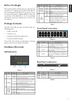
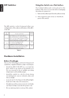
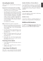
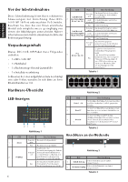
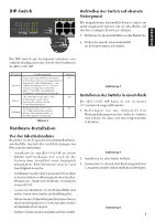
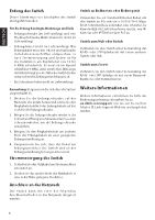
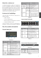
ENGLISH DIP Switches 5 6 7 85 6 7 8 15 26 37 48 1 5 26 37 48 Using the Switch on a Flat Surface The included rubber pads can be placed on the 9 10 11 12 13 14 15 16 17 18 1000 Link / Act bottom of the device to prevent it from damaging the surface it is placed on. 9 10 11 12 13 14 15 16 1. Remove the rubber pads from the adhesive strip. 2. Stick one pad on each corner on the bottom panel of the switch. The DIP switches on the front panel allow easy configuration of the advanced features of the DSS100E-18P DIP Switch Function Controlled Standard Switch all ports can communicate with each other port and work as a common Unmanaged Switch. *1 to 16 port supports Power over Ethernet and transmit data at 10/100 Mbps.** 1 to 8 port supports port priority to optimize port cache. Isolate 1 to 16 port can't communicate with each other, but each of them can communicate with port 17 and 18. Extend The data rate of 9 to 16 port is limited to 10Mbps, whereas the maximum transmission distance of the port is increased to 250 meters. Default On Off Off Table 4 Figure 4 Mounting the Switch in a Rack The DSS-100E-18P can be mounted into a standard 19" server rack. 1. Attach the included mounting brackets to the sides of the switch and secure them using the provided screws. Hardware Installation Before You Begin Observe the following precautions to help prevent shutdowns, equipment failures, and personal injury: • Install the DSS-100E-18P in a cool and dry place. Refer to the technical specifications in the user manual for the acceptable operating temperature and humidity ranges. • Install the switch in a site free from strong electromagnetic sources, vibration, dust, and direct sunlight. • Leave at least 10 cm of space to the left and righthand side of the switch for ventilation. • Visually inspect the power connector and make sure that it is fully secured to the power cord. • Do not stack any devices on top of the switch. Figure 5 2. Install the switch into the rack. 3. Use the screws that were provided with the rack to secure the switch to the rack. Figure 6 2
-
 1
1 -
 2
2 -
 3
3 -
 4
4 -
 5
5 -
 6
6 -
 7
7 -
 8
8 -
 9
9 -
 10
10 -
11
-
12
-
13
-
14
-
15
-
16
-
17
-
18
-
19
-
20
 |
 |
