Dell Alienware Area-51 ALX Service Manual
Dell Alienware Area-51 ALX Manual
 |
View all Dell Alienware Area-51 ALX manuals
Add to My Manuals
Save this manual to your list of manuals |
Dell Alienware Area-51 ALX manual content summary:
- Dell Alienware Area-51 ALX | Service Manual - Page 1
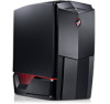
ALIENWARE® AREA-51 SERVICE MANUAL 01 /01 - Dell Alienware Area-51 ALX | Service Manual - Page 2
of your computer. CAUTION: A CAUTION indicates either potential damage to hardware or loss of data and tells you how to avoid the problem. WARNING: is strictly prohibited. Trademarks used in this manual: Alienware is a registered trademark of Alienware Corporation. Dell is a trademark of Dell Inc - Dell Alienware Area-51 ALX | Service Manual - Page 3
7 Turning Off Your Computer 7 Before Working Inside Your Computer 8 CHAPTER 2: TECHNICAL OVERVIEW 9 System Board Components 11 Master I/O Board Components 12 CHAPTER 3: CHASSIS 13 Removing the Left Side-Panel 15 Replacing the Left Side-Panel 15 Removing the Right Side-Panel 16 Replacing the - Dell Alienware Area-51 ALX | Service Manual - Page 4
CHAPTER 8: FRONT BEZEL 44 Removing the Front Bezel 46 Replacing the Front Bezel 46 CHAPTER 9: FANS 47 Removing the PCI Fan 49 Replacing the PCI Fan 50 Removing the Hard-Drive Fan(s 51 Replacing the Hard-Drive Fan(s 52 CHAPTER 10: ACTIVE-VENTING ASSEMBLY 53 Removing the Active-Venting - Dell Alienware Area-51 ALX | Service Manual - Page 5
Battery 89 Replacing the Coin-Cell Battery 90 Removing the Theater-Lighting Batteries 91 Replacing the Theater-Lighting Batteries 92 CHAPTER 19: SYSTEM SETUP 93 Overview 95 Entering System Setup 95 System Setup Options 96 Clearing CMOS Settings 102 Flashing the BIOS 103 CONTENTS 05 /05 - Dell Alienware Area-51 ALX | Service Manual - Page 6
BEGIN This manual provides procedures for removing and installing the components in your computer. Unless otherwise noted, each procedure assumes that the following conditions exist: • You have performed the steps in "Turning Off Your Computer" on page 7 and "Before Working Inside Your Computer" on - Dell Alienware Area-51 ALX | Service Manual - Page 7
then click Shut Down. The computer turns off after the operating system shutdown process finishes. 3. Ensure that the computer is turned off. If your computer did not automatically turn off when you shut down the operating system, press and hold the power button until the computer turns off. 07 /07 - Dell Alienware Area-51 ALX | Service Manual - Page 8
the following steps before you begin working inside the computer. 1. Ensure that the work surface is flat and clean. 2. Ensure that sufficient space exists to support the computer with the side panel(s) opened. 3. Turn off your computer (see "Turning Off Your Computer" on page 7) and all attached - Dell Alienware Area-51 ALX | Service Manual - Page 9
CHAPTER 2: TECHNICAL OVERVIEW CHAPTER 2: TECHNICAL OVERVIEW CHAPTER 2: TECHNICAL OVERVIEW 09 /09 - Dell Alienware Area-51 ALX | Service Manual - Page 10
Technical Overview WARNING: Before working inside your computer, read the safety information that shipped with your computer. For additional safety best practices information, see the Regulatory Compliance Homepage at www.dell.com/regulatory_compliance. CHAPTER 2: TECHNICAL OVERVIEW 010 /010 - Dell Alienware Area-51 ALX | Service Manual - Page 11
x16 card slot (PCI_E3) 11 SATA connectors (SATA 1-SATA 6) for 25 PCI-Express x1 card slot hard drives (PCI_E2) 12 password reset jumper (PASSWORD) 26 PCI-Express x16 card slot (PCI_E1) 13 CMOS reset jumper (CLEAR_CMOS) 27 internal eSATA header (SATA9) 14 front-panel connector (FP1) 011 /011 - Dell Alienware Area-51 ALX | Service Manual - Page 12
Master I/O Board Components 1 2 34 76 5 CHAPTER 2: TECHNICAL OVERVIEW 1 fan connector (FANCONN1) 2 PCI-fan connector (PCI_FAN1) 3 hard-drive fan connector (HDD_FAN2) 4 hard-drive fan connector (HDD_FAN1) 5 system-board USB header (MB_USB1) 6 bluetooth-module connector (BLUETOOTH) 7 wireless- - Dell Alienware Area-51 ALX | Service Manual - Page 13
CHAPTER 3: CHASSIS CHAPTER 3: CHASSIS CHAPTER 3: CHASSIS 013 /013 - Dell Alienware Area-51 ALX | Service Manual - Page 14
cover(s) (including side panels, bezels, filler brackets, front-panel inserts, etc.) removed. CAUTION: Only a certified service technician should perform repairs on your computer. Damage due to servicing that is not authorized by Dell™ is not covered by your warranty. CHAPTER 3: CHASSIS CAUTION: To - Dell Alienware Area-51 ALX | Service Manual - Page 15
the hinges. Replacing the Left Side-Panel 1. Follow the instructions in "Before You Begin" on page 6. 2. If the left side-panel was removed completely from the chassis, align it with the hinges and replace it in the chassis. 3. Push the left side-panel against the side of the computer until it locks - Dell Alienware Area-51 ALX | Service Manual - Page 16
. Replacing the Right Side-Panel 1. Follow the instructions in "Before You Begin" on page 6. 2. If the right side-panel was removed completely from the chassis, align it with the hinges and replace it in the chassis. 3. Push the right side-panel against the side of the computer until it locks into - Dell Alienware Area-51 ALX | Service Manual - Page 17
cable from the SIDE_LEFT connector on the master I/O board. 4. Press out to release the left bottom-panel clamps that secure the left bottom-panel to the chassis. 5. Remove the left bottom-panel. Replacing the Left Bottom-Panel 1. Follow the instructions in "Before You Begin" on page 6. 2. Route - Dell Alienware Area-51 ALX | Service Manual - Page 18
master I/O board. 4. Remove the hard-drive fans (see "Removing the Hard-Drive Fan(s)" on page 51). 5. Press out to release the right bottom-panel clamps that secure the right bottom-panel to the chassis. 6. Remove the right bottom-panel. Replacing the Right Bottom-Panel 1. Follow the instructions - Dell Alienware Area-51 ALX | Service Manual - Page 19
Follow the instructions in "Before You Begin" on page 6. 2. Remove the left side-panel (see "Removing the Left Side-Panel" on page 15). 3. Disconnect the chassis-intrusion switch cable from the master I/O board connector. 4. Slide the chassis-intrusion switch towards the top of the computer and then - Dell Alienware Area-51 ALX | Service Manual - Page 20
CHAPTER 4: SHROUDS CHAPTER 4: SHROUDS CHAPTER 4: SHROUDS 020 /020 - Dell Alienware Area-51 ALX | Service Manual - Page 21
WARNING: Before working inside your computer, read the safety information that shipped with your computer. For additional panels, bezels, filler brackets, front-panel inserts, etc.) removed. CAUTION: Only a certified service technician should perform repairs on your computer. Damage due to servicing - Dell Alienware Area-51 ALX | Service Manual - Page 22
1. Follow the instructions in "Before You Begin" on page 6. 2. Lift the release panel and open the left side-panel 3. Press the PCI-shroud button to release the PCI shroud and then rotate the PCI shroud away from the computer. 4. To remove the PCI-shroud completely from the chassis: a. Remove the - Dell Alienware Area-51 ALX | Service Manual - Page 23
shroud to the chassis. 4. Connect the drive-bay shroud cables to the master I/O board connectors. 5. Replace the PCI shroud (see "Replacing the PCI Shroud" on page 22). 6. Replace the left side-panel (see "Replacing the Left Side-Panel" on page 15). 7. Connect your computer and devices to electrical - Dell Alienware Area-51 ALX | Service Manual - Page 24
the specifications in your Desktop Manual or in the Comprehensive Specifications at support.dell.com for information on the memory supported by your computer. Install only memory modules that are supported by your computer. NOTE: Memory modules purchased from Dell or Alienware are covered under your - Dell Alienware Area-51 ALX | Service Manual - Page 25
Memory Module(s) WARNING: Before working inside your computer, read the safety information that shipped with your computer panels, bezels, filler brackets, front-panel inserts, etc.) removed. CAUTION: Only a certified service technician should perform repairs on your computer. Damage due to servicing - Dell Alienware Area-51 ALX | Service Manual - Page 26
Removing Memory Module(s) 1. Follow the instructions in "Before You Begin" on page 6. 2. Lift the release panel and open the left side-panel. 3. Locate the memory-module connectors on the system board (see "System Board Connectors" on page 11). CAUTION: The memory module(s) may become very hot - Dell Alienware Area-51 ALX | Service Manual - Page 27
position. NOTE: If the memory module is not installed properly, the computer may not boot. 4. If you insert the memory module correctly, the securing clips snap into the cutouts at each end of the memory module. 5. Close the left-side panel. 6. Connect your computer and devices to electrical outlets - Dell Alienware Area-51 ALX | Service Manual - Page 28
and automatically updates the system configuration information. To confirm the amount of memory installed in the computer: Windows Vista® Click Start → Control Panel→ System and Maintenance. Windows® 7 Click Start → Control Panel→ System and Security→ System. CHAPTER 5: MEMORY MODULE(S) 028 /028 - Dell Alienware Area-51 ALX | Service Manual - Page 29
CHAPTER 6: PCI AND PCI-EXPRESS CARDS CHAPTER 6: PCI AND PCI-EXPRESS CARDS CHAPTER 6: PCI AND PCI-EXPRESS CARDS 029 /029 - Dell Alienware Area-51 ALX | Service Manual - Page 30
WARNING: Before working inside your computer, read the safety information that shipped with your computer. For additional panels, bezels, filler brackets, front-panel inserts, etc.) removed. CAUTION: Only a certified service technician should perform repairs on your computer. Damage due to servicing - Dell Alienware Area-51 ALX | Service Manual - Page 31
Express Cards 1. Follow the instructions in "Before You Begin" on page 6. 2. Lift the release panel and open the left side-panel. 3. Remove the PCI the card out of the connector. NOTE: If you are not replacing a card, install a filler bracket in the empty card-slot opening. 2 3 1 PCI-Express x16 - Dell Alienware Area-51 ALX | Service Manual - Page 32
the instructions in Align the card with the connector on the system board. 4. Place the card in the seated in the connector. If you are installing the PCI-Express card into the x16 card on page 22). 7. Close the left side-panel. 8. Connect your computer and devices to electrical outlets, and then - Dell Alienware Area-51 ALX | Service Manual - Page 33
CHAPTER 7: DRIVES CHAPTER 7: DRIVES CHAPTER 7: DRIVES 033 /033 - Dell Alienware Area-51 ALX | Service Manual - Page 34
when handling the hard drive. NOTE: Dell does not guarantee compatibility or provide support for hard drives from sources other than Dell or Alienware. NOTE: If you are installing a hard drive from a source other than Dell or Alienware, you need to install an operating system, drivers, and utilities - Dell Alienware Area-51 ALX | Service Manual - Page 35
Removing Optical Drive(s) 1. Follow the instructions in "Before You Begin" on page 6. 2. Press the AlienHead to lower the drive panel. 1 drive panel CHAPTER 7: DRIVES 1 2 2 AlienHead 035 /035 - Dell Alienware Area-51 ALX | Service Manual - Page 36
Lift the release panel and open the left side-panel. 4. Disconnect the power cable and the data cable from the back of the optical drive. 5. Pull the securing tab on the optical-drive bracket and slide the optical drive out through the front of the computer. 3 2 1 CHAPTER 7: DRIVES 4 1 data cable - Dell Alienware Area-51 ALX | Service Manual - Page 37
through the front of the computer. 4. Pull the securing tab on the optical-drive bracket and slide the optical drive into the optical-drive bay, until the securing tab snaps into place. 5. Connect the power cable and the data cable to the optical drive. 6. Close the left side-panel. 7. Connect your - Dell Alienware Area-51 ALX | Service Manual - Page 38
Removing the Media Card Reader 1. Follow the instructions in "Before You Begin" on page 6. 2. Press the AlienHead to lower the drive panel. 1 drive panel CHAPTER 7: DRIVES 1 2 2 AlienHead 038 /038 - Dell Alienware Area-51 ALX | Service Manual - Page 39
Lift the release panel and open the left side-panel. 4. Disconnect the FlexBay cable from the back of the Media Card Reader. 2 5. Pull the securing tab on the FlexBay bracket and slide the Media Card Reader out through the front of the computer. 1 CHAPTER 7: DRIVES 3 1 FlexBay cable 2 Media - Dell Alienware Area-51 ALX | Service Manual - Page 40
Reader 1. Follow the instructions in "Before You Begin the FlexBay bracket and slide the FlexBay filler out through the front of the computer. 4. Pull the securing tab on the FlexBay bracket and slide Close the left side-panel. 7. Connect your computer and devices to electrical outlets, and then turn them - Dell Alienware Area-51 ALX | Service Manual - Page 41
Removing Hard Drive(s) 1. Follow the instructions in "Before You Begin" on page 6. 2. Lift the release panel and open the right side-panel. 1 3. Press the hard-drive release tabs simultaneously and slide the hard drive towards the top and out of the computer. 2 CHAPTER 7: DRIVES 1 hard-drive - Dell Alienware Area-51 ALX | Service Manual - Page 42
4. If you are removing a solid-state drive (SSD): a. Remove the four screws that secure the SSD to the hard-drive bracket. b. Slide and lift the SSD out of the hard-drive bracket. 1 2 3 1 screws (4) 2 hard-drive bracket CHAPTER 7: DRIVES 3 SSD 042 /042 - Dell Alienware Area-51 ALX | Service Manual - Page 43
Replacing Hard Drive(s) 1. Follow the instructions in "Before You Begin" on page 6. 1 NOTE: See the documentation that shipped with your new hard-drive to verify that it is configured for your computer. 2. If you are replacing an SSD: a. Replace the SSD in the hard-drive bracket. 2 b. Replace - Dell Alienware Area-51 ALX | Service Manual - Page 44
CHAPTER 8: FRONT BEZEL CHAPTER 8: FRONT BEZEL CHAPTER 8: FRONT BEZEL 044 /044 - Dell Alienware Area-51 ALX | Service Manual - Page 45
Front Bezel WARNING: Before working inside your computer, read the safety information that shipped with your computer. For panels, bezels, filler brackets, front-panel inserts, etc.) removed. CAUTION: Only a certified service technician should perform repairs on your computer. Damage due to servicing - Dell Alienware Area-51 ALX | Service Manual - Page 46
Right Side-Panel" on page 16). 4. Disconnect the front-bezel cables from the master I/O board connectors. 5. Release the front-bezel clamps that secure the front bezel to the chassis. 6. Pull the front bezel away from the front of the computer. Replacing the Front Bezel 1. Follow the instructions in - Dell Alienware Area-51 ALX | Service Manual - Page 47
CHAPTER 9: FANS CHAPTER 9: FANS CHAPTER 9: FANS 047 /047 - Dell Alienware Area-51 ALX | Service Manual - Page 48
WARNING: Before working inside your computer, read the safety information that shipped with your computer. For additional panels, bezels, filler brackets, front-panel inserts, etc.) removed. CAUTION: Only a certified service technician should perform repairs on your computer. Damage due to servicing - Dell Alienware Area-51 ALX | Service Manual - Page 49
Follow the instructions in "Before You Begin" on page 6. 2. Remove the left side-panel (see "Removing the Left Side-Panel" on page 15). 3. Remove the drive-bay shroud (see "Removing the Drive-Bay Shroud" on page 23). 4. Disconnect the PCI-fan cable from the PCI_FAN1 connector on the master I/O board - Dell Alienware Area-51 ALX | Service Manual - Page 50
Fan 1. Follow the instructions in "Before You master I/O board (see "Master I/O Board Connectors" on page 12). 7. Replace the drive-bay shroud (see "Replacing the Drive-Bay Shroud" on page 23). 8. Replace the left side-panel (see "Replacing the Left Side-Panel" on page 15). 9. Connect your computer - Dell Alienware Area-51 ALX | Service Manual - Page 51
-Drive Fan(s) 1. Follow the instructions in "Before You Begin" on page 6. 2. Remove the left side-panel (see "Removing the Left Side-Panel" on page 15). 3. Remove the PCI shroud (see "Removing the PCI Shroud" on page 22). 2 4. If you are removing the left hard-drive fan, remove the power supply - Dell Alienware Area-51 ALX | Service Manual - Page 52
-drive fan shroud. 4. Push the hard-drive fan into the chassis until the hard-drive fan handle clicks into place. 5. Connect the hard-drive fan cables to the HDD_FAN1 and HDD_FAN2 connectors on the master I/O board (see "Master I/O Board Connectors" on page 12). 6. If you removed the power supply - Dell Alienware Area-51 ALX | Service Manual - Page 53
CHAPTER 10: ACTIVE-VENTING ASSEMBLY CHAPTER 10: ACTIVE-VENTING ASSEMBLY CHAPTER 10: ACTIVE-VENTING ASSEMBLY 053 /053 - Dell Alienware Area-51 ALX | Service Manual - Page 54
WARNING: Before working inside your computer, read the safety information that shipped with your computer. For additional panels, bezels, filler brackets, front-panel inserts, etc.) removed. CAUTION: Only a certified service technician should perform repairs on your computer. Damage due to servicing - Dell Alienware Area-51 ALX | Service Manual - Page 55
Removing the Active-Venting Assembly 1. Follow the instructions in "Before You Begin" on page 6. 2. Remove the left side-panel (see "Removing the Left Side-Panel" on page 15). 3. Remove the right side-panel (see "Removing the Right Side-Panel" on page 16). 4. Disconnect the active-venting assembly - Dell Alienware Area-51 ALX | Service Manual - Page 56
master I/O board. 7. Replace the right side-panel (see "Replacing the Right Side-Panel" on page 16). 8. Replace the left side-panel (see "Replacing the Left Side-Panel" on page 15). CAUTION: Before turning on the computer, replace all screws and ensure that no stray screws remain inside the computer - Dell Alienware Area-51 ALX | Service Manual - Page 57
CHAPTER 11: TOP I/O PANEL CHAPTER 11: TOP I/O PANEL CHAPTER 11: TOP I/O PANEL 057 /057 - Dell Alienware Area-51 ALX | Service Manual - Page 58
I/O Panel WARNING: Before working inside your computer, read the safety information that shipped with your computer. For panels, bezels, filler brackets, front-panel inserts, etc.) removed. CAUTION: Only a certified service technician should perform repairs on your computer. Damage due to servicing - Dell Alienware Area-51 ALX | Service Manual - Page 59
the left side-panel (see "Removing the Left Side-Panel" on page 15). 3. Remove the right side-panel (see "Removing the Right Side-Panel" on page 16). 4. Remove the front bezel (see "Removing the Front Bezel" on page 46). 5. Remove the ten screws that secure the hard-drive shroud to the chassis - Dell Alienware Area-51 ALX | Service Manual - Page 60
the top I/O panel cables from the system board connectors and remove the cables from their routing guides. 9. Remove the four screws that secure the top I/O panel to the chassis. 10. Pull the top I/O panel off the chassis. CHAPTER 11: TOP I/O PANEL 1 2 1 screws (4) 2 top I/O panel 060 /060 - Dell Alienware Area-51 ALX | Service Manual - Page 61
hard-drive shroud to the chassis. 8. Replace the front bezel (see "Replacing the Front Bezel" on page 46). 9. Replace the right side-panel (see "Replacing the Right Side-Panel" on page 16). 10. Replace the left side-panel (see "Replacing the Left Side-Panel" on page 15). 11. Connect your computer - Dell Alienware Area-51 ALX | Service Manual - Page 62
CHAPTER 12: BLUETOOTH MODULE CHAPTER 12: BLUETOOTH MODULE CHAPTER 12: BLUETOOTH MODULE 062 /062 - Dell Alienware Area-51 ALX | Service Manual - Page 63
WARNING: Before working inside your computer, read the safety information that shipped with your computer. For additional panels, bezels, filler brackets, front-panel inserts, etc.) removed. CAUTION: Only a certified service technician should perform repairs on your computer. Damage due to servicing - Dell Alienware Area-51 ALX | Service Manual - Page 64
the Bluetooth Module 1. Follow the instructions in "Before You Begin" on page 6. 2. Remove the left side-panel (see "Removing the Left Side-Panel" on page 15). 3. Disconnect the Bluetooth®-module cable from the BLUETOOTH connector on the master I/O board (see "Master I/O Board Connectors" on page 12 - Dell Alienware Area-51 ALX | Service Manual - Page 65
module to the chassis. 4. Connect the Bluetooth-module cable to the BLUETOOTH connector on the master I/O board (see "Master I/O Board Connectors" on page 12). 5. Replace the left side-panel (see "Replacing the Left Side-Panel" on page 15). 6. Connect your computer and devices to electrical - Dell Alienware Area-51 ALX | Service Manual - Page 66
CHAPTER 13: LIQUID-COOLING ASSEMBLY CHAPTER 13: LIQUID-COOLING ASSEMBLY CHAPTER 13: LIQUID-COOLING ASSEMBLY 066 /066 - Dell Alienware Area-51 ALX | Service Manual - Page 67
WARNING: Before working inside your computer, read the safety information that shipped with your computer. For additional panels, bezels, filler brackets, front-panel inserts, etc.) removed. CAUTION: Only a certified service technician should perform repairs on your computer. Damage due to servicing - Dell Alienware Area-51 ALX | Service Manual - Page 68
1. Follow the instructions in "Before You Begin" on page 6. 2. Remove the left side-panel (see "Removing the Left Side-Panel" on page 15). 3. Disconnect the liquid-cooling assembly cable from the liquid-cooling assembly. 4. Push the release latch towards the back of the computer to release the - Dell Alienware Area-51 ALX | Service Manual - Page 69
assembly in the chassis and rotate the liquid‑cooling assembly upwards until it snaps into place. 3. Connect the liquid-cooling assembly cable to the liquid-cooling assembly. 4. Replace the left side-panel (see "Replacing the Left Side-Panel" on page 15). 5. Connect your computer and devices to - Dell Alienware Area-51 ALX | Service Manual - Page 70
CHAPTER 14: PROCESSOR CHAPTER 14: PROCESSOR CHAPTER 14: PROCESSOR 070 /070 - Dell Alienware Area-51 ALX | Service Manual - Page 71
WARNING: Before working inside your computer, read the safety information that shipped with your computer. For additional panels, bezels, filler brackets, front-panel inserts, etc.) removed. CAUTION: Only a certified service technician should perform repairs on your computer. Damage due to servicing - Dell Alienware Area-51 ALX | Service Manual - Page 72
Removing the Processor 1. Follow the instructions in "Before You Begin" on page 6. 2. Remove the left side-panel (see "Removing the Left Side-Panel" on page 15). 3. Remove the PCI shroud (see "Removing the PCI Shroud" on page 22). 4. Remove the liquid-cooling assembly (see "Removing the Liquid- - Dell Alienware Area-51 ALX | Service Manual - Page 73
Processor 1. Follow the instructions in "Before You Begin" on page 6. 2. Unpack the new processor, being careful not to touch the underside of the processor. CAUTION: You must position the processor correctly in the socket to avoid permanent damage to the processor and the computer when you turn on - Dell Alienware Area-51 ALX | Service Manual - Page 74
(see "Replacing the Liquid-Cooling Assembly" on page 69). 10. Replace the PCI shroud (see "Replacing the PCI Shroud" on page 22). 11. Replace the left side-panel (see "Replacing the Left Side-Panel" on page 15). 12. Connect your computer and devices to electrical outlets, and then turn them on - Dell Alienware Area-51 ALX | Service Manual - Page 75
CHAPTER 15: MASTER I/O BOARD CHAPTER 15: MASTER I/O BOARD CHAPTER 15: MASTER I/O BOARD 075 /075 - Dell Alienware Area-51 ALX | Service Manual - Page 76
Master I/O Board WARNING: Before working inside your computer, read the safety information that shipped with your computer panels, bezels, filler brackets, front-panel inserts, etc.) removed. CAUTION: Only a certified service technician should perform repairs on your computer. Damage due to servicing - Dell Alienware Area-51 ALX | Service Manual - Page 77
Removing the Master I/O Board 1. Follow the instructions in "Before You Begin" on page 6. 2. Remove the left side-panel (see "Removing the Left Side-Panel" on page 15). 3. Remove the PCI shroud (see "Removing the PCI Shroud" on page 22). 4. Disconnect all cables from the master I/O board. Note the - Dell Alienware Area-51 ALX | Service Manual - Page 78
master I/O board. 5. Replace the PCI shroud (see "Replacing the PCI Shroud" on page 22). 6. Replace the left side-panel (see "Replacing the Left Side-Panel" on page 15). CAUTION: Before turning on the computer, replace all screws and ensure that no stray screws remain inside the computer. Failure - Dell Alienware Area-51 ALX | Service Manual - Page 79
CHAPTER 16: SYSTEM BOARD CHAPTER 16: SYSTEM BOARD CHAPTER 16: SYSTEM BOARD 079 /079 - Dell Alienware Area-51 ALX | Service Manual - Page 80
panels, bezels, filler brackets, front-panel inserts, etc.) removed. CAUTION: Only a certified service technician should perform repairs on your computer. Damage due to servicing incorrectly could damage your system board. For information on contacting Dell, see your Desktop Manual. CAUTION: To avoid - Dell Alienware Area-51 ALX | Service Manual - Page 81
can re-route them correctly after installing the new system board. 9. Remove the two screws that secure the system-board tray to the chassis. 10. Carefully remove the system-board tray from the chassis. NOTE: Do not remove the system board from the system-board tray. The system-board tray is shipped - Dell Alienware Area-51 ALX | Service Manual - Page 82
shroud (see "Replacing the PCI Shroud" on page 22). 10. Replace the left side-panel (see "Replacing the Left Side-Panel" on page 15). CAUTION: Before turning on the computer, replace all screws and ensure that no stray screws remain inside the computer. Failure to do so may result in damage to the - Dell Alienware Area-51 ALX | Service Manual - Page 83
CHAPTER 17: POWER SUPPLY CHAPTER 17: POWER SUPPLY CHAPTER 17: POWER SUPPLY 083 /083 - Dell Alienware Area-51 ALX | Service Manual - Page 84
Power Supply WARNING: Before working inside your computer, read the safety information that shipped with your computer. panels, bezels, filler brackets, front-panel inserts, etc.) removed. CAUTION: Only a certified service technician should perform repairs on your computer. Damage due to servicing - Dell Alienware Area-51 ALX | Service Manual - Page 85
Power Supply 1. Follow the instructions in "Before You Begin" on page 6. 2. Remove the left side-panel (see "Removing the Left Side-Panel" on page 15). 3. Remove the PCI shroud (see "Removing the PCI Shroud" on page 22). 4. Push the power-supply handle inwards to unlock it. 5. Using the power-supply - Dell Alienware Area-51 ALX | Service Manual - Page 86
the front of the computer. 3. Connect the power-supply cable connector to the power supply. 4. Slide the power supply completely into the chassis. 5. Push the power-supply handle inwards to lock it. 6. Replace the PCI shroud (see "Replacing the PCI Shroud" on page 22). 7. Replace the left side-panel - Dell Alienware Area-51 ALX | Service Manual - Page 87
CHAPTER 18: BATTERY CHAPTER 18: BATTERY CHAPTER 18: BATTERY 087 /087 - Dell Alienware Area-51 ALX | Service Manual - Page 88
to the manufacturer's instructions. WARNING: To guard against electrical shock, always unplug your computer from the electrical outlet before opening the side panel(s). WARNING: Do not operate your equipment with any cover(s) (including side panels, bezels, filler brackets, front-panel inserts, etc - Dell Alienware Area-51 ALX | Service Manual - Page 89
Record all the screens in system setup (see "System Setup" on page 93) so that you can restore the correct settings after the new battery has been installed. 2. Follow the instructions in "Before You Begin" on page 6. 3. Lift the release panel and open the left side-panel. 4. Remove the PCI shroud - Dell Alienware Area-51 ALX | Service Manual - Page 90
PCI shroud (see "Replacing the PCI Shroud" on page 22). 4. Close the left-side panel. 5. Connect your computer and devices to electrical outlets, and then turn them on. 6. Enter system setup (see "Entering System Setup" on page 95) and restore the settings you recorded before removing the battery - Dell Alienware Area-51 ALX | Service Manual - Page 91
Removing the Theater-Lighting Batteries 1. Follow the instructions in "Before You Begin" on page 6. 2. Lift the release panel and open the left side-panel. 3. Open the theater-lighting battery-compartment door. 4. Remove the two theater-lighting batteries. CHAPTER 18: BATTERY 1 2 1 theater- - Dell Alienware Area-51 ALX | Service Manual - Page 92
1. Follow the instructions in "Before You Begin" on page 6. 2. Insert the two new batteries (rechargeable AA, NiMH type) in the theater- lighting battery compartment. 3. Close the theater-lighting battery-compartment door. 4. Close the left side-panel. 5. Connect your computer and devices to - Dell Alienware Area-51 ALX | Service Manual - Page 93
CHAPTER 19: SYSTEM SETUP CHAPTER 19: SYSTEM SETUP CHAPTER 19: SYSTEM SETUP 093 /093 - Dell Alienware Area-51 ALX | Service Manual - Page 94
System Setup WARNING: Before working inside your computer, read the safety information that shipped with your computer. panels, bezels, filler brackets, front-panel inserts, etc.) removed. CAUTION: Only a certified service technician should perform repairs on your computer. Damage due to servicing - Dell Alienware Area-51 ALX | Service Manual - Page 95
hard drive installed. Before you use System Setup, it is recommended that you write down the current System Setup information for future reference. CAUTION: Do not change the settings in System Setup unless you are an expert computer user. Certain changes can cause your computer to work incorrectly - Dell Alienware Area-51 ALX | Service Manual - Page 96
Setup Options NOTE: The items listed in this section may or may not appear exactly as listed depending on your computer model and installed devices. System Information Product Name Displays the product name. BIOS Version Displays the BIOS version, number, and date information. Input Service - Dell Alienware Area-51 ALX | Service Manual - Page 97
Features 1st Boot Device 2nd Boot Device Hard Disk Drives CD/DVD Drives CPU Configuration XD Bit Capability Intel® Speedstep® tech Intel® C State Tech CHAPTER 19: SYSTEM SETUP Displays the first boot device. Displays the second boot device. Sets the hard drive boot priority. The items displayed are - Dell Alienware Area-51 ALX | Service Manual - Page 98
Allows you to configure the integrated hard drive controller to AHCI or RAID. Allows you to set the wait time for SATA or CD/DVD in AHCI mode. Power Management Setup Suspend Mode AC Recovery Remote Wakeup Auto Power On Frequency/Voltage Control CPU Speed Memory Speed Current QPI Speed QPI Frequency - Dell Alienware Area-51 ALX | Service Manual - Page 99
Frequency/Voltage Control CPU Core (Non-Turbo) Ratio Advance DRAM Configuration Overclock Configuration : SYSTEM SETUP Advance DRAM Configuration Submenu Memory-Z Opens submenu to display the SPD configuration for each memory module. Advanced Memory Settings Allows you to toggle to Manual mode - Dell Alienware Area-51 ALX | Service Manual - Page 100
Submenu Turbo Mode TDP Limit Override CHAPTER 19: SYSTEM SETUP Allows you to program the power thresholds for the processor while in turbo mode. Overvoltage Configuration Submenu CPU Temperature Sensor VCore Dynamic CPU VCore Offset DDR3 Memory Voltage IOH Voltage QPI and Uncore Voltage Displays - Dell Alienware Area-51 ALX | Service Manual - Page 101
the supervisor password. Allows you to set or change the user password. You cannot use the user password to make change to the BIOS settings. Exit Exit Options Provides options to Save Changes and Exit, Discard Changes and Exit, and Load Optimal Defaults. CHAPTER 19: SYSTEM SETUP 0101 /0101 - Dell Alienware Area-51 ALX | Service Manual - Page 102
CMOS reset jumper pins 1 and 2. 8. Replace the PCI shroud (see "Replacing the PCI Shroud" on page 22). 9. Replace the left side-panel (see "Replacing the Left Side-Panel" on page 15). 10. Connect your computer and devices to electrical outlets, and then turn them on. CHAPTER 19: SYSTEM SETUP 0102 - Dell Alienware Area-51 ALX | Service Manual - Page 103
available or when replacing the system board. To flash the BIOS: 1. Turn on the computer. 2. Visit support.dell.com. 3. Select your country and language. 4. Click Drivers & Downloads. 5. Locate the BIOS update file for your computer: NOTE: The Service Tag for your computer is located on a label next
-
 1
1 -
 2
2 -
 3
3 -
 4
4 -
 5
5 -
 6
6 -
 7
7 -
8
-
9
-
10
-
11
-
12
-
13
-
14
-
15
-
16
-
17
-
18
-
19
-
20
-
21
-
22
-
23
-
24
-
25
-
26
-
27
-
28
-
29
-
30
-
31
-
32
-
33
-
34
-
35
-
36
-
37
-
38
-
39
-
40
-
41
-
42
-
43
-
44
-
45
-
46
-
47
-
48
-
49
-
50
-
51
-
52
-
53
-
54
-
55
-
56
-
57
-
58
-
59
-
60
-
61
-
62
-
63
-
64
-
65
-
66
-
67
-
68
-
69
-
70
-
71
-
72
-
73
-
74
-
75
-
76
-
77
-
78
-
79
-
80
-
81
-
82
-
83
-
84
-
85
-
86
-
87
-
88
-
89
-
90
-
91
-
92
-
93
-
94
-
95
-
96
-
97
-
98
-
99
-
100
-
101
-
102
-
103
 |
 |

01
01
/
A
L
IENWARE
®
AREA-51
SERVICE MANUAL