Dell Alienware Area-51 ALX Service Manual - Page 23
Removing the Drive-Bay Shroud, Replacing the Drive-Bay Shroud
 |
View all Dell Alienware Area-51 ALX manuals
Add to My Manuals
Save this manual to your list of manuals |
Page 23 highlights
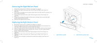
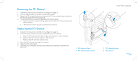
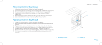
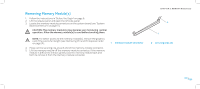
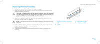
Removing the Drive-Bay Shroud 1. Follow the instructions in "Before You Begin" on page 6. 2. Remove the left side-panel (see "Removing the Left Side-Panel" on page 15). 3. Remove the PCI shroud (see "Removing the PCI Shroud" on page 22). 4. Disconnect the drive-bay shroud cables from the master I/O board connectors. 5. Remove the two screws that secure the drive-bay shroud to the chassis. 6. Slide and pull the drive-bay shroud away from the computer. Replacing the Drive-Bay Shroud 1. Follow the instructions in "Before You Begin" on page 6. 2. Align the screw holes on the drive-bay shroud with the screw holes on the chassis. 3. Replace the two screws that secure the drive-bay shroud to the chassis. 4. Connect the drive-bay shroud cables to the master I/O board connectors. 5. Replace the PCI shroud (see "Replacing the PCI Shroud" on page 22). 6. Replace the left side-panel (see "Replacing the Left Side-Panel" on page 15). 7. Connect your computer and devices to electrical outlets, and then turn them on. 1 drive-bay shroud CHAPTER 4: SHROUDS 1 2 2 screws (2) 023 /023
-
 1
1 -
2
-
3
-
4
-
5
-
6
-
7
-
8
-
9
-
10
-
11
-
12
-
13
-
14
-
15
-
16
-
17
-
 18
18 -
 19
19 -
 20
20 -
 21
21 -
 22
22 -
 23
23 -
 24
24 -
 25
25 -
 26
26 -
 27
27 -
 28
28 -
29
-
30
-
31
-
32
-
33
-
34
-
35
-
36
-
37
-
38
-
39
-
40
-
41
-
42
-
43
-
44
-
45
-
46
-
47
-
48
-
49
-
50
-
51
-
52
-
53
-
54
-
55
-
56
-
57
-
58
-
59
-
60
-
61
-
62
-
63
-
64
-
65
-
66
-
67
-
68
-
69
-
70
-
71
-
72
-
73
-
74
-
75
-
76
-
77
-
78
-
79
-
80
-
81
-
82
-
83
-
84
-
85
-
86
-
87
-
88
-
89
-
90
-
91
-
92
-
93
-
94
-
95
-
96
-
97
-
98
-
99
-
100
-
101
-
102
-
103
 |
 |
