Dell Alienware M17X R3 Mobile Manual - Page 81
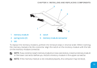
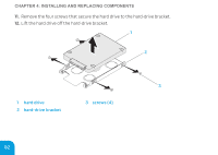
connector on the system board.
 |
View all Dell Alienware M17X R3 manuals
Add to My Manuals
Save this manual to your list of manuals |
Page 81 highlights
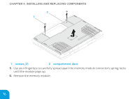
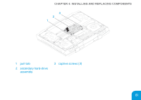
CHAPTER 4: INSTALLING AND REPLACING COMPONENTS 2 1 1 screws (2) 2 compartment door 5. Loosen the three captive screws on the primary hard-drive assembly (HDD0). 6. Using the pull-tab, lift the primary hard-drive assembly to disconnect it from the connector on the system board. 7. Lift the primary hard-drive assembly out of the computer base. 79
-
 1
1 -
2
-
3
-
4
-
5
-
6
-
7
-
8
-
9
-
10
-
11
-
12
-
13
-
14
-
15
-
16
-
17
-
18
-
19
-
20
-
21
-
22
-
23
-
24
-
25
-
26
-
27
-
28
-
29
-
30
-
31
-
32
-
33
-
34
-
35
-
36
-
37
-
38
-
39
-
40
-
41
-
42
-
43
-
44
-
45
-
46
-
47
-
48
-
49
-
50
-
51
-
52
-
53
-
54
-
55
-
56
-
57
-
58
-
59
-
60
-
61
-
62
-
63
-
64
-
65
-
66
-
67
-
68
-
69
-
70
-
71
-
72
-
73
-
74
-
75
-
 76
76 -
 77
77 -
 78
78 -
 79
79 -
 80
80 -
 81
81 -
 82
82 -
 83
83 -
 84
84 -
 85
85 -
 86
86 -
87
-
88
-
89
-
90
-
91
-
92
-
93
-
94
-
95
-
96
-
97
-
98
-
99
-
100
-
101
-
102
-
103
-
104
-
105
-
106
-
107
-
108
-
109
-
110
-
111
-
112
-
113
-
114
-
115
-
116
-
117
-
118
-
119
-
120
-
121
-
122
-
123
-
124
-
125
-
126
-
127
-
128
 |
 |

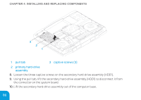
CHAPTER 4: IN°TALLING AND REPLACING COMPONENT°
79
1
2
1
screws (2)
2
compartment door
5.
Loosen the three captive screws on the primary hard‑drive assembly (HDD0).
6.
Using the pull‑tab, lift the primary hard‑drive assembly to disconnect it from the
connector on the system board.
7.
Lift the primary hard‑drive assembly out of the computer base.