Dell Brocade 300 QuickStart Guide - Page 4
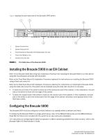
Site Planning and Safety Guidelines - rack mount
 |
View all Dell Brocade 300 manuals
Add to My Manuals
Save this manual to your list of manuals |
Page 4 highlights
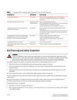
TABLE 1 Brocade 5000 Installation Tasks, Estimated Time, and Items Required Installation Task Time Estimate Items Required Installing rack mount kit Mounting and securing switch in rack Installing power cables and serial cable and configuring IP addresses Installing Ethernet cables and configuring the Brocade 5000 switch name, policies, domain ID, PIDs, or additional system parameters Installing SFP optical transceivers Attaching fiber-optic cables, cable ties, and cable guides 30 minutes Refer to the Brocade Slide Rack Mount Kit Installation Procedure or Brocade Fixed Rack Mount Kit Installation Procedure. Depends on which rack installation Refer to the appropriate document: Brocade Slide Rack Mount Kit Installation Procedure Brocade Fixed Rack Mount Kit Installation Procedure Brocade 5000 Mounting Ears Installation Procedure 20 minutes Power cables and serial cable (provided in Brocade 5000 accessory kit) Workstation computer with a serial port or terminal server port and a terminal emulator application (such as HyperTerminal) IP address for switch 20 minutes Ethernet cabling (optional) for Telnet access All other configuration parameters optional. Refer to the Fabric OS Administrator's Guide for PID information. 30 minutes SFP optical transceivers 60 minutes Fiber-optic cables, cable ties, and cable guides Site Planning and Safety Guidelines WARNING To ensure adequate cooling, install the chassis with the nonport side facing the air-intake aisle. Verify that a minimum of 47 cubic feet/minute (79.8 cubic meters/hour) of air flow is available to the air intake vents on the nonport side of the switch. This prevents the fans from pulling in heated exhaust air. To install and operate the switch successfully, ensure that the following requirements are met: • The primary AC input is 90-264 VAC (switch auto-senses input voltage), 47-440 Hz. • The primary outlet, is correctly wired, protected by a circuit breaker, and grounded in accordance with local electrical codes. • The supply circuit, line fusing, and wire size are adequate, as specified by the electrical rating on the switch nameplate. For power supply information, refer to the Brocade 5000 Hardware Reference Manual. To ensure adequate cooling, install the switch with the nonport side, which contains the air intake vents, facing a cool-air aisle. Verify that the ambient air temperature does not exceed 40° Celsius (104° Fahrenheit) and that the ambient humidity remains between 20 percent and 85 percent while the switch is operating. If installing the switch in a cabinet: • The cabinet must be a standard EIA cabinet. • Plan a cabinet space that is 1 rack unit high (1.75 inches; 4.44 cm), 19 inches (48.3 cm) wide, and at least 24 inches (61 cm) deep. 6 of 12 Brocade 5000 QuickStart Guide Publication Number: 53-1000425-01
-
 1
1 -
 2
2 -
 3
3 -
 4
4 -
 5
5 -
 6
6 -
 7
7 -
 8
8 -
 9
9 -
 10
10
 |
 |
