Dell Brocade 300 QuickStart Guide - Page 6
Installing the Brocade 5000 in an EIA Cabinet, Configuring the Brocade 5000
 |
View all Dell Brocade 300 manuals
Add to My Manuals
Save this manual to your list of manuals |
Page 6 highlights
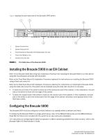
Figure displays the port-side view of the Brocade 5000 switch. 5 4 1 System Console Port 2 System Ethernet Port 3 Power Supply/Fan Assembly Field Replaceable Unit (2x) 4 Power Cord Retainer (2x) 5 Switch ID Pull Out Tab FIGURE 1 Port Side View of the Brocade 5000 Installing the Brocade 5000 in an EIA Cabinet Refer to the Brocade 5000 Mounting Ears Installation Procedure for installing the Brocade 5000 in an EIA cabinet using the mounting ears provided with the switch. Refer to the Fixed Rack Mount Kit Installation Procedure (optional) for instructions on installing the Brocade 5000 using a fixed rack mount kit. Refer to the Slide Rack Mount Kit Installation Procedure (optional) for instructions on installing the Brocade 5000 using the slide rack mount kit. The switch can be installed using the slide rack mount kit in two ways: • To allow the port side of the switch to slide out of the exhaust-air side of the cabinet. In this installation, the port side of the switch is flush with the edge of the cabinet. • To allow the nonport side of the switch to slide out the cool-air side of the cabinet. In this installation, the port side of the switch is set three inches back from the edge of the cabinet, allowing a more gradual bend in the fiber-optic cables. Configuring the Brocade 5000 The Brocade 5000 must be configured correctly before it can operate within a network and fabric. If configuring the Brocade 5000 in a single-switch setup, refer to the EZSwitch Setup CD and the EZSwitchSetup Read Me First document included with the switch for an easy and quick installation. For instructions on configuring the switch to operate in a fabric containing switches from other vendors, refer to the Brocade Fabric OS Administrator's Guide. 8 of 12 Brocade 5000 QuickStart Guide Publication Number: 53-1000425-01
-
 1
1 -
 2
2 -
 3
3 -
 4
4 -
 5
5 -
 6
6 -
 7
7 -
 8
8 -
 9
9 -
 10
10
 |
 |
