Dell DAE Setup Guide - Page 6
Step 1 - Set DAE2 Enclosure Address(es), Step 2 - Set Up Fibre Channel Loops
 |
View all Dell DAE manuals
Add to My Manuals
Save this manual to your list of manuals |
Page 6 highlights
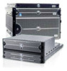
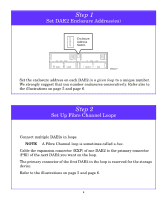
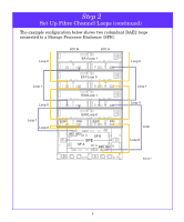
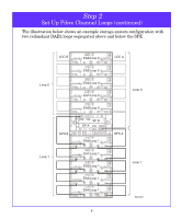
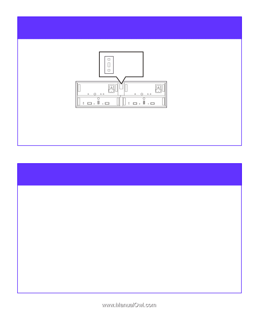
Step 1 Set DAE2 Enclosure Address(es) _ Enclosure 0 Address + Switch EMC2310 Set the enclosure address on each DAE2 in a given loop to a unique number. We strongly suggest that you number enclosures consecutively. Refer also to the illustrations on page 5 and page 6. Step 2 Set Up Fibre Channel Loops Connect multiple DAE2s in loops. NOTE A Fibre Channel loop is sometimes called a bus. Cable the expansion connector (EXP) of one DAE2 to the primary connector (PRI) of the next DAE2 you want on the loop. The primary connector of the first DAE2 in the loop is reserved for the storage device. Refer to the illustrations on page 5 and page 6. 4
-
 1
1 -
 2
2 -
 3
3 -
 4
4 -
 5
5 -
 6
6 -
 7
7 -
 8
8 -
 9
9 -
 10
10 -
 11
11 -
 12
12 -
13
-
14
 |
 |
4
Step 1
Set DAE2 Enclosure Address(es)
Set the enclosure address on each DAE2
in a given loop
to a unique number.
We strongly suggest that you number enclosures consecutively. Refer also to
the illustrations on page 5 and page 6.
EMC2310
Enclosure
Address
Switch
+
_
0
Step 2
Set Up Fibre Channel Loops
Connect multiple DAE2s in loops.
NOTE
A Fibre Channel loop is sometimes called a
bus
.
Cable the expansion connector (EXP) of one DAE2 to the primary connector
(PRI) of the next DAE2 you want on the loop.
The primary connector of the first DAE2 in the loop is reserved for the storage
device.
Refer to the illustrations on page 5 and page 6.