Dell Force10 S25-01-GE-24V Installing the S25N and S25V Systems - Page 17
Power, S25N, Power over Ethernet (PoE) Support
 |
View all Dell Force10 S25-01-GE-24V manuals
Add to My Manuals
Save this manual to your list of manuals |
Page 17 highlights
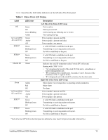
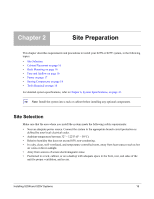
Power S25N The S25N comes standard with two 150W AC power supplies with auto-sensing 110/220V AC receptacles, each of which, when connected to a power source, is capable of supplying all required power to the switch. When both are connected to power sources, they act in load-sharing mode; see Figure 3 on page 10. Use the power cords shipped with the S25N to connect it to AC power outlets, ideally on separate circuits. Several versions of the power cord are available, based on country requirements. Caution: The power supply cord is used as the main disconnect device; ensure that the socket-outlet is located/installed near the equipment and is easily accessible. S25V As shown in Figure 2 on page 10, the right side (as you face the back of the unit) of the S25V contains one auto-sensing 110/220V AC receptacle and a -48V DC terminal block. When both the AC and DC power supplies are connected on the S25V, it uses them in load-sharing mode. If the 470W DC Backup Power Supply provided by Force10 is connected to the Current Sharing connection on the back of the S25V, the system uses the DC and AC in current-sharing mode, which is load-sharing up to 470W, while also allowing them to provide a total of 940W. The 470W PSU is oversized in order to support PoE, as described next. See also Backup Power Components on page 31. For details on connecting to a power source, see Supplying Power on page 29. Power over Ethernet (PoE) Support Along with the optional DC power supply noted above, the S25V includes an internal 470W power supply that supports both the operation of the switch and an independent power distribution system to supply power to the 24 copper Ethernet ports that support the IEEE 802.3af standard for Power over Ethernet (PoE). Connect only powered devices that adhere to IEEE 802.3af. The total PoE power budget for the switch is between 320W and 790W, depending on the power sources available. If the external 470W DC Force10 Redundant Power Supply (catalog # S50-01-PSU-V) is attached to the Current Sharing terminal (see Chapter 4, Installing Backup Power, on page 31), you can use the power-budget command in FTOS to convert its use to current-sharing mode to provide up to 790W of PoE. Each port can provide a maximum of 15.4W, subject to the power budget, voltage, power priority, and power limit settings. PoE is, by default, enabled globally on a first-come, first-serve basis, until it exceeds the total available power. Alternatively, the switch administrator can use the CLI to allocate power on a per-port and a per-stack-unit basis, with per-port power limits and port prioritization. For a brief introduction in this guide to the PoE commands, see Connecting S25V Ethernet Ports with PoE on page 38. Installing S25N and S25V Systems 17
-
 1
1 -
2
-
3
-
4
-
5
-
6
-
7
-
8
-
9
-
10
-
11
-
 12
12 -
 13
13 -
 14
14 -
 15
15 -
 16
16 -
 17
17 -
 18
18 -
 19
19 -
 20
20 -
 21
21 -
 22
22 -
23
-
24
-
25
-
26
-
27
-
28
-
29
-
30
-
31
-
32
-
33
-
34
-
35
-
36
-
37
-
38
-
39
-
40
-
41
-
42
-
43
-
44
-
45
-
46
-
47
-
48
-
49
-
50
-
51
-
52
-
53
-
54
 |
 |